16
User Guide
| OI-LLT100-EN Rev. D
LLT100
Laser level transmitter
5.2 Setting initial parameters with LCD interface
Once you powered on the LLT100, you can set the basic
parameters from the
Easy Setup
configuration menu. This is
one reason why the Advanced mode is strongly recommended:
it allows for configuration of every function in the instrument.
5.2.1 Setting level or ullage parameters
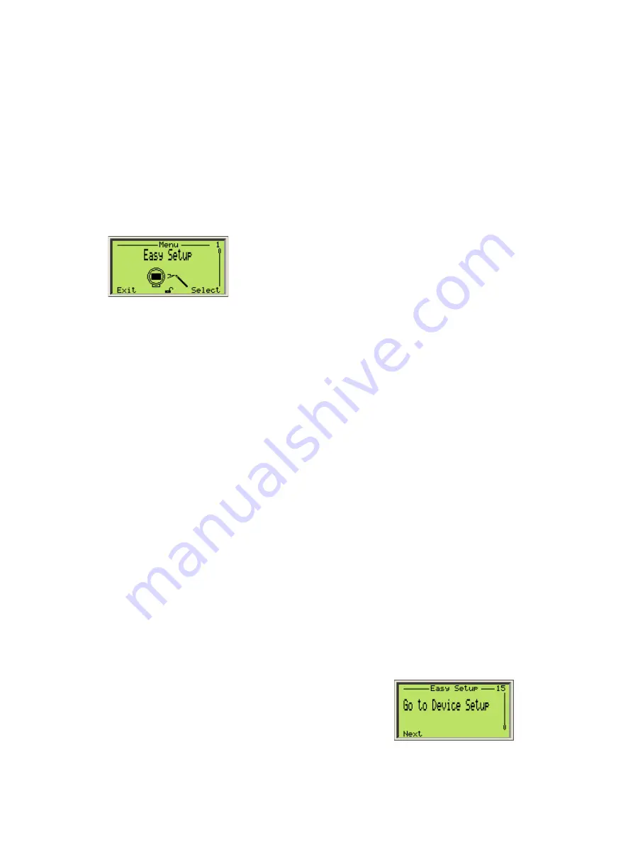
1. Once the LLT100 is on, access
Easy Setup
in the
configuration menus and press
Select
.
2. Select the interface language and press
Next
.
English
is
selected by default.
3. Select the measurement mode and press
Next
.
Standard
is selected by default. You select the
measurement mode based on the intended application of
the instrument being configured (for more information, see
Table 2 on page 17).
4. Select the level unit and press
Next
. This is the unit used
in level and ullage measurements, and when calculating
volumes.
5. Edit the vessel height (URP, or “ullage reference point”) so
that it corresponds to the height of the vessel to be monitored
(for more information, see “General model” on page 15).
6. Edit the sensor offset (for more information, see “Setting
the sensor offset” on page 21).
7. Select the output type for the 4 – 20 mA process value (PV).
8. Edit the Vessel Empty (LRV, or lower reference value) level
(4 mA).
9. Edit the Vessel Full (URV, or upper reference value) level
(20 mA). The default value is the vessel height entered
previously.
10. (if necessary) Enable the Filling Rate feature (for more
information on the filling rate feature, see section 7.4
“Configuring the filling rate” on page 24).
11. (if necessary) Create a tag for the instrument. This “tag”,
comprised of alphanumeric characters, is intended to
simplify identifying the location of the LLT100 (on the
network, in the plant, etc.)
12. Once all
Easy Setup
parameters have been set, press
Next
to exit the
Easy Setup
menu and go back to the
default Operator page.
5.2.2 Setting volume parameters
1. Once the LLT100 is on, access
Easy Setup
in the
configuration menus and press
Select
.
2. Select the interface language and press
Next
.
English
is
selected by default.
3. Select the measurement mode and press
Next
.
Standard
is selected by default. You select the
measurement mode based on the intended application of
the instrument being configured (for more information, see
Table 2 on page 17).
4. Select the level unit and press
Next
. This is the unit used
in level and ullage measurements, and when calculating
volumes.
5. Edit the vessel height (URP, or “ullage reference point”) so
that it corresponds to the height of the vessel to be monitored
(for more information, see “General model” on page 15).
6. Edit the sensor offset (for more information, see “Setting
the sensor offset” on page 21).
7. Select
Volume
for the 4 – 20 mA process value (PV) output
type .
8. Select the unit for the
Volume
output. The liter (
l
) is the
default value, but other volume units are available.
9. Edit the minimum volume. The default value is
0
.
10. Edit the maximum volume. The default value is
1 000 000
liters (or the equivalent in the unit of your choice).
11. (if necessary) Enable the Filling Rate feature (for more
information on the filling rate feature, see section 7.4
“Configuring the filling rate” on page 24).
12. (if necessary) Create a tag for the instrument. This “tag”,
comprised of alphanumeric characters, is intended to
simplify identifying the location of the LLT100 (on the
network, in the plant, etc.)
13. Once you have configured the initial volume measurement
parameters, you still need to setup your linearization table
in the Device Setup menu (8 “Configuring linearization” on
page 25) as requested at the end of the
Easy Setup
menu.
14. Once all
Easy Setup
parameters have been set, press
Next
to exit the
Easy Setup
menu and go back to the
default Operator page.
Summary of Contents for LLT100
Page 8: ...This page intentionally left blank ...
Page 10: ...This page intentionally left blank ...
Page 18: ...This page intentionally left blank ...
Page 22: ...This page intentionally left blank ...
Page 26: ...This page intentionally left blank ...
Page 44: ...This page intentionally left blank ...
Page 50: ...This page intentionally left blank ...
Page 66: ...This page intentionally left blank ...
Page 67: ......


