32
User Guide
| OI-LLT100-EN Rev.DE
LLT100
Laser level transmitter
11.3.2 Dusty conditions
In applications where dust may be present (even in very small
quantities) it is recommended that a dust tube be used (see
Appendix B, “Accessories”, on page 53). The dust tube is a
very simple and effective device designed to prevent dust from
settling on the lens. The dust tube accessory allows use of the
LLT100 in most dusty applications.
NOTICE
The dust tube should also be used in outdoor locations
to help prevent detector saturation from sunlight.
In extremely dusty conditions (i.e., during a filling process),
if the signal is lost for too long, the measurement may be
temporarily unavailable. For more information on choosing the
appropriate measurement mode, see Table 2, “Measurement
modes”, on page 17
.
11.3.3 Foggy conditions
In extremely foggy conditions, (i.e., during a filling process),
if the signal is lost for too long, the measurement may be
temporarily unavailable. For more information on choosing the
appropriate measurement mode, see Table 2, “Measurement
modes”, on page 17
.
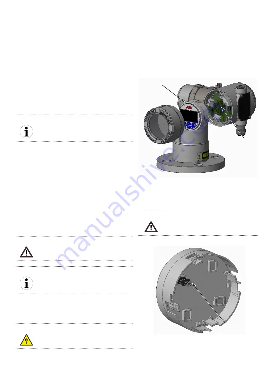
11.4 Rotating the LCD
When the LCD is installed, it is possible to rotate that display
in one of four different positions at 90° intervals.
CAUTION
Property damage
For Ex d and/or flameproof installations, see note
“Securing the housing cover in flameproof/explosion
proof areas” on page 8.
NOTICE
Observe applicable ESD protection measures to avoid
damaging instrument circuits.
To rotate the LCD:
1. Make sure that the instrument is powered off.
2. Unscrew the housing cover on the LCD side (hazardous
area warnings must be heeded).
CAUTION
Sharp edges
Do not grab the instrument by its threaded interface.
Thread edges are sharp and constitute a risk of personal
injury (see Figure 3 on page 8).
3. Pull the LCD away from the communication board.
Figure 21
Rotating the LCD
4. Reposition the LCD connector according to the new
desired position.
5. Push back the LCD module on the communication board,
making sure that the four plastic locks are properly fixed.
CAUTION
Property damage
Be careful not to bend the connection pins when
pushing the LCD back in.
Figure 22
Connection pins on back of LCD
6. Hand tighten the housing cover back in place.
LCD board
Communication
board
Connection pins
on back of LCD
board
Summary of Contents for LLT100
Page 8: ...This page intentionally left blank ...
Page 10: ...This page intentionally left blank ...
Page 18: ...This page intentionally left blank ...
Page 22: ...This page intentionally left blank ...
Page 26: ...This page intentionally left blank ...
Page 44: ...This page intentionally left blank ...
Page 50: ...This page intentionally left blank ...
Page 66: ...This page intentionally left blank ...
Page 67: ......


