LMT S E R I E S |
M AG N E TOS T R I C T I V E L E V EL T R A N SM I T T ER | O I/L M T 10 0/ 2 0 0 - EN R E V. B
13
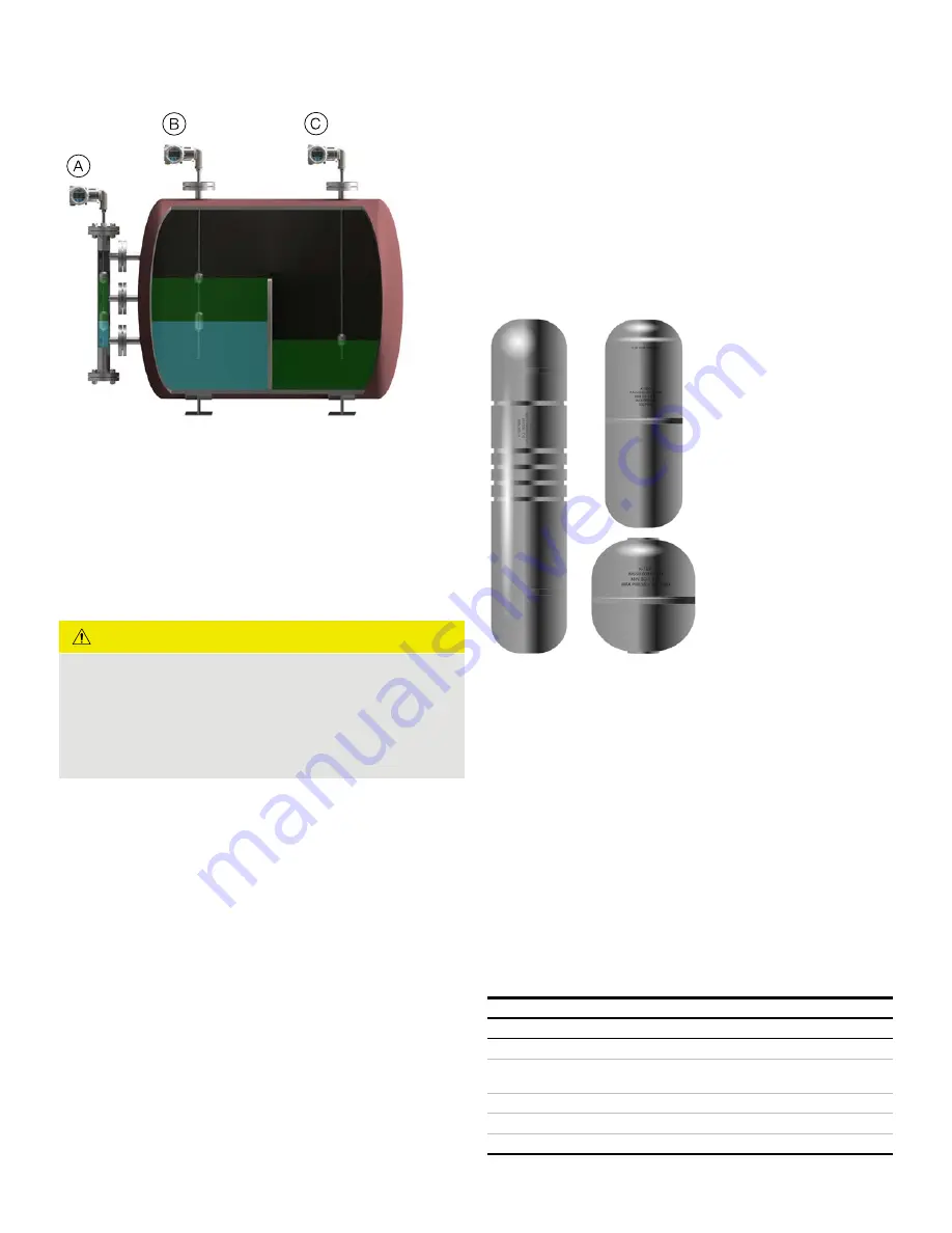
Figure 5 LMT100 Mounting
LMT100 Transmitters installations:
A
Installed in external chambers in a level and interface measurement
application
B
Installed directly into vessel, measuring level and interface level
C
Installed directly into vessel measuring level only
CAUTION
Do not run an external magnet on the outside of the sensor
and then take the magnet off This leaves residual magnetic
properties on the wire, causing a false echo if a magnet is
used, be sure to run the magnet from the sensor elbow to
the probe tip to ensure no residual magnetic field is
present
Compression fittings
When fitted with a compression fitting as the process
connection, the sensor tube is shipped with a set of TEFLON®
ferrules and a set of metal ferrules in a separate bag The
TEFLON® ferrules are only intended for use in applications with
operating pressures at or below 3 4 bar (50 psig) and process
temperatures at or below 204°C (400°F) For higher operating
pressures or temperatures or for permanent installation,
replace the TEFLON® ferrules with metal ferrules
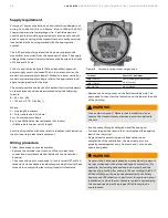
Floats
The float is a key component of the LMT Series transmitter that
must be matched to the medium in respect of density, pressure
resistance and material durability Every LMT float is precisely
engineered to customer application, ensuring optimal accuracy
and performance Precisely spaced magnets create a 360°
magnetic field coverage, safeguarding level transmitter and
gauge performance, even the most challenging applications
Several materials of construction available including Titanium,
Monel®, Hastelloy® C, Stainless Steel, and Plastics Tefzel®,
Halar®, TEFLON® S protective coatings are also available
During installation, it may be necessary to remove the float and
spacer (if included) from the sensor tube For proper
operation, the float must be reinstalled using the proper
orientation Floats may be marked with “Top for SPM” or “Top
for LMT” These ends of the float must face the transmitter
head Other floats may be marked with an arrow indicating the
proper orientation If a float is etched with information but
does not indicate a proper orientation, it will be bidirectional
and can be installed in either direction
Figure 6 Floats
IMPORTANT NOTE
During installation, take care not to bend the probe tube, and
protect the float from shock and impact loads If the float is
removed during installation, it must be slid back onto the probe
tube afterwords for LMT100 with the “TOP” marking oriented
towards the sensor head end, to enable correct measurements
to be made For LMT200, the float must be installed in the
chamber in proper orientation
Sensor wells
Certain transmitter options have the sensor tube inserted into
a sensor well These options allow the sensor tube and housing
to be removed for service without breaking the seal on the
vessel These options include (consult model number) W1, W2,
W3, W4, W5, W6, C3, C4, W7, J4 and J5
Sensor Wells
Model
Sensor Type
Sensor Well
W1, W2,
½ in rigid
5/8 in. tube
W4, W5, W6,
C3, C4
5/8 in. rigid
¾ in pipe (typical)
W3,
½ in flexible stainless
5/8 in. tube
W7
5/8 in. flexible plastic
1 in. sectioned tube
J4, J5
½ in rigid
5/8 in. tube with TEFLON® jacket


