20
LMT S E R I E S |
M AG N E TOS T R I C T I V E L E V EL T R A N SM I T T ER | O I/L M T 10 0/ 2 0 0 - EN R E V. B
Supply requirement
For signal / power connections, use twisted, stranded pairs of
wiring, 18 to 22 AWG / 0 8 to 0 35 mm
2
Ø up to 1500 m (5,000ft)
Longer loops require lower gauge wire If a shielded wire is
used, the shield should be grounded only at one end, not both
ends In case of wiring at the transmitter end, use the terminal
located inside the housing marked with the appropriate
symbol
The 4-20 mA output signal and the dc power supply to the
transmitter are carried from the same pair of wires The supply
voltage at the transmitter terminals must be between the limits
of 12 Vdc and 42 Vdc
For Ex ia and intrinsically safe (FM and Canadian) approval
power supply must not exceed 30 Vdc In some countries, the
maximum power supply voltage is limited to a lower value For
maximum power supply voltage, refer to the appropiate local
approval designation for the area
The actual possible line length of the electrical circuit depends
on the resistance and can be estimated using the following
formula:
R = 46 x Vcc - 552
L = (23 x Vcc - 276 - 0 5 x Rs) /
Where:
L = Line length in meters
R = Total resistance in Ω (ohms)
Vcc = Power supply voltage
Rs = Any additional series resistance in Ω (ohms)
= Cable resistance per unit of length
Avoid routing cables with other electrical cables (with inductive
load) or near large electrical equipment
Wiring procedure
Follow these steps to wire transmitter:
• Remove the terminal cap from one of the two electrical
connection ports located at both sides of the transmitter
housing
• The connection ports may have a ½-inch internal NPT or M20
threads Various adapters and bushings can be fitted to these
threads to comply with plant wiring (conduit) standards
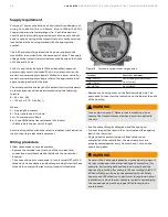
Figure 18 Terminal board without surge option
Terminal
Function / Comment
PWR/COMM +
Power supply, current output /
HART® output
PWR/COMM -
EXT METER
Not assigned
• Remove the housing cover on the field terminals side The
user needs to then view the indication on the label at the neck
of the housing
WARNING
In an explosion-proof / flame-proof installation, do not
remove the transmitter covers when power is supplied to
the unit
• Run the cable through cable gland and the open port
• Connect the positive lead to the + terminal and the negative
lead to the – terminal
• Plug and seal the electrical ports Ensure that upon
completion of the installation, the electrical ports are
properly sealed against entry from rain and / or corrosive
vapors and gases
WARNING
General risks Cable, cable gland and unused port plug must
be in accordance with the intended type of protection (for
example, intrinsically safe and explosion-proof) and the
degree of protection (for example, IP6x according to IEC EN
60529 or NEMA 4x) See also the addendum for Ex Safety
Aspects and IP Protection In particular, for explosion-proof
installation, remove the red, temporary plastic cap and plug
the unused opening with a plug certified for explosion
containment


