LMT S E R I E S |
M AG N E TOS T R I C T I V E L E V EL T R A N SM I T T ER | O I/L M T 10 0/ 2 0 0 - EN R E V. B
21
• If applicable, install the wiring with a drip loop Arrange the
drip loop so the bottom is lower than the conduit connections
andthe transmitter housing
• Place the housing cover back, turn it to seat the O-ring into
the housing and then continue to hand-tighten until the cover
contacts the housing, metal-to-metal In Ex-d (explosion-
proof) installation, lock the cover rotation by turning the set
nut
Grounding
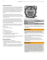
A terminal is available on both the outside of the housing and in
the plug for grounding (PE) the transmitter Both terminals are
electrically connected to one another (see Figure 19)
Figure 19 Ground connection on transmitter housing
All transmitters are supplied with an external ground
connection for protective grounding Wire this ground
connection to a suitable earth ground For a transmitter
measuring loop, an earth ground should maintain a resistance
of 5 ohms or less Use a heavy-duty conductor, at least 15 AWG /
1 6 mm
2
Ø
WARNING - General risks.
A protective grounding connection is absolutely necessary
to ensure personnel protection, to protect against surge (in
case of installation of this option) and to prevent explosions
in potentially explosive environments
Integrated lightning protection
The transmitter housing must be connected using the
grounding terminal (PE) by means of a short connection with
the equipotential bonding Equipotential bonding minimum
diameter of 4 mm (AWG 12) is required throughout the cable
routing area
In case of transmitters with integrated lightning protection
(optional), the intrinsically safe circuit is connected to the
equipotential bonding for safety reasons
Figure 20 Terminal board with surge option
IMPORTANT NOTE
Test voltage withstand capability can no longer be ensured
when this protective circuit is used


