LMT S E R I E S |
M AG N E TOS T R I C T I V E L E V EL T R A N SM I T T ER | O I/L M T 10 0/ 2 0 0 - EN R E V. B
23
Failure Mode
Activation via hardware switch
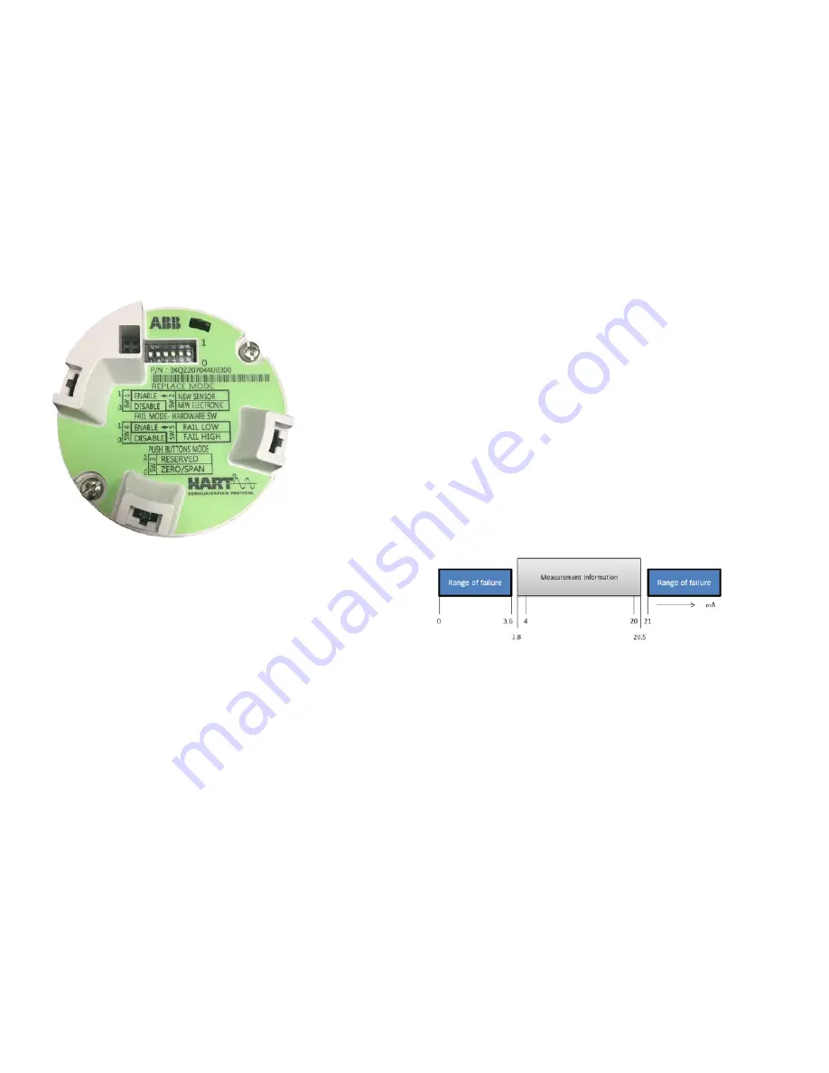
To activate this function, it is necessary to proceed as detailed
below:
• Remove instrument cover and standard HMI display (if
installed)
• On the communication board, place dip switch 4 in the “up”
position
• On the communication board, place the dip switch #5 in the
up position for fail low or down position for fail high
Figure 23 Communication board
Failure mode via device software
Failure mode via device software is possible Please refer to
the Section 8 “Operation” of this manual under “Menu: Process
Alarm”
Analog and HART communication models
If the level applied falls within the values indicated on the name
plate, the output current will be between 4 and 20 mA If the
level applied falls outside the set range, the output current will
be between 3 5 mA and 4 mA If the level applied exceeds the
set limit, the output current will be between 20 mA and 22 5 mA
(depending on the respective configuration)
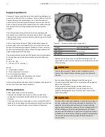
Standard setting for error detection (alarm)
3 .6 mA / 21 mA
The graphical user interface (DTM) or the HMI integral display
(if installed) can be used to diagnose the error
IMPORTANT NOTE
A brief interruption in the power supply results in initialization
of the electronics (program restarts)
Verify proper power-up of the transmitter
Use a mA meter to measure the output current When power is
applied, the output should go to 4 00 mA for at least one (1)
second and then to either the measured level or an alarm
condition output If this does not occur, the transmitter may
not be receiving enough power or the main electronic is
defective Excessive current of about 21 mA is also an indication
of improper powerup or defective electronics (see Figure 24)
Valid current loop outputs
•
21 mA
– High alarm (the HMI display indicates level as ----) If
the communication board switch #5 is set to fail high, a loss
of signal or a problem with the configuration or a
malfunction will cause the output to be set to the alarm
condition of 20 99 mA
•
20 .5 mA
– Saturated high
When the level increases above the 20 mA point, the output
will continue up to 20 5 mA and then saturates at this value
until the level moves back down again
•
4 .00-20 .00 mA
– Normal output range
•
3 .8 mA
– Saturated low
When the level decreases below the 4 mA point, the output
continues down to 3 8 mA and then saturates at this value
until the level moves back up again
•
3 .6 mA
– Low alarm (the HMI display indicates level as ----) If
the electronics board, switch 5 is set to FAIL LOW, a loss of
signal or a problem with the configuration or a malfunction
causes the output to be set to the alarm condition or 3 6 mA
Figure 24 NAMUR NE-43 Diagnostic Fault Range
Range and span consideration
The LMT Series data sheets provide all the information
concerning the range and span limits in relation to the model
and sensor codes
URL Upper Range Limit of a specific sensor This represents
the measured value’s highest set point that the
transmitter can be adjusted to
LRL
Lower Range Limit of a specific sensor This represents
the lowest value of the measured value that the
transmitter can be adjusted to measure
URV Upper Range Value The measured value’s highest value
by which the transmitter is calibrated
LRV
Lower Range Value The lowest value of the measured
value to which the transmitter is calibrated
SPAN The algebraic difference between the Upper and Lower
Range Values The minimum span is the minimum value
that can be used without degradation of the specified
performance


