50
LMT S E R I E S |
M AG N E TOS T R I C T I V E L E V EL T R A N SM I T T ER | O I/L M T 10 0/ 2 0 0 - EN R E V. B
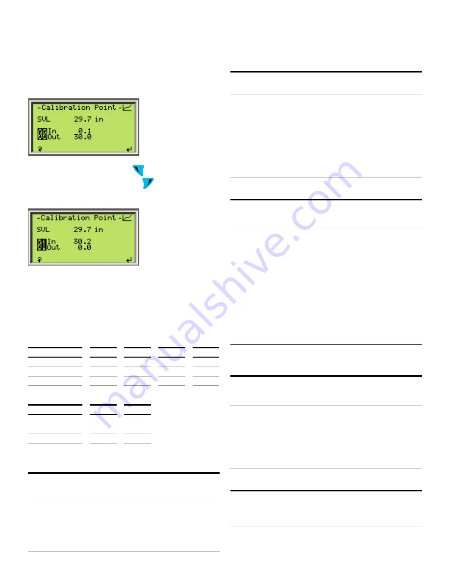
The steps above could be repeated for any of the 2 points if
additional fine adjustment is needed
NOTICE: The order in which the points are set is irrelevant
To exit the calibration menu press
to scroll until either
point 00 or 01 is highlighted and then
to exit the
calibration and return to the previous menu
Calibration examples
1
Use of validation rule for Level Calibration
In the examples below the Input span is 100 – 0 = 100cm, as
such Output span must be between 95 and 105 cm (‘Out’ values
range must be within 5% of the ‘In’ values range)
Examples of acceptable calibration:
Top Mount
Case 1
Case 2
Case 3
Case 4
Point
In
Out
Out
Out
Out
00
0 ->
0
15
25
0
01
100 ->
100
115
130
95
Examples of rejected calibration:
Bottom Mount
Case 4
Case 5
Point
In
LVL
LVL
00
100 ->
94
116
01
0 ->
0
10
2
Calibration moving float to both 0 and 100% points (Wet
Calibration)
Requirements
• Probe Length = 220 cm
• Mounting: Bottom or Top
• ML = 200 cm
Procedure
• Place the float at 0%
• Capture sensor value (SVL) to assign it to <In> of
point 01
• Set 0 cm for <Out> of point 01
• Place the float at 100%
• Capture SVL to assign it to <In> of point 00
• Set 200 cm for <Out> of point 00
• End
3
Calibration moving float only to 0% point only (Partially Wet
calibration)
Conditions
• Probe Length = 220 cm
• Mounting: Bottom or Top
• ML = 200 cm
Procedure
• Place the float at 0%
• Capture sensor value (SVL) assign it to <In> of point
01
• Set 0 cm for <Out> of point 01
• ake the <In> of point 01 and add 200 cm for bottom
mount transmitters or substract 200 cm for top
mounted transmitters
• Ex: if <In> of point 01 of top mounted unit was 210.5
cm then <In> for point 00 will be 10.5 cm
• Use the resulting sum for <In> of point 00
• Set 200 cm for parameter <Out> of point 00
• End
4
Calibration stretching the zero beyond trim points
Conditions
• LMT200
• Probe Length = 220 cm
• Mounting: Top
• ML = 200 cm
Procedure
• Determine the lower point to measure
• Place the float in that position and inspect the
signal in the waveform screen to make sure that
there is enough signal amplitude, that is not
merging with the end of the probe
• Back off from that position until the signal is not
merging with the end of the probe and the
amplitude is the same as in the begining of the
probe
• Measure the distance from the desired zero mark
• Capture SVL for parameter <In> of point 01
• Set the measured distance for parameter <Out> of
point 01
• Place the float at 100%
• Capture SVL for parameter <In> of point 00
• Set 200 cm for parameter <Out> of point 00
• End
5
Calibration when float cannot be moved to 0% or 100%
points (Dry Calibration)
Conditions
• Probe Length = 220 cm
• Mounting: Bottom or Top
• ML = 200 cm
• Current level 35%
Procedure
• Capture SVL for parameter <In> of point 01
• Set parameter <Out> of point 01 to 70 cm (35%)
• Take the <In> parameter of point 01 and add 130 cm
(remaining 65%) for bottom mount units or
substract 130 cm for top mounted units.
• Use the resulting sum for parameter <In> of point
00
• Set 200 cm for parameter <Out> of point 00
• End
6
Changing mount orientation
Conditions
• LMT200
• Probe Length = 220 cm
• Mounting: Bottom or Top
• ML = 200 cm
• Previously calibrated for specific mount


