background image

LST100 – Ultrasonic level transmitter | 

OI/LST100-EN  13

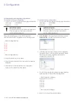
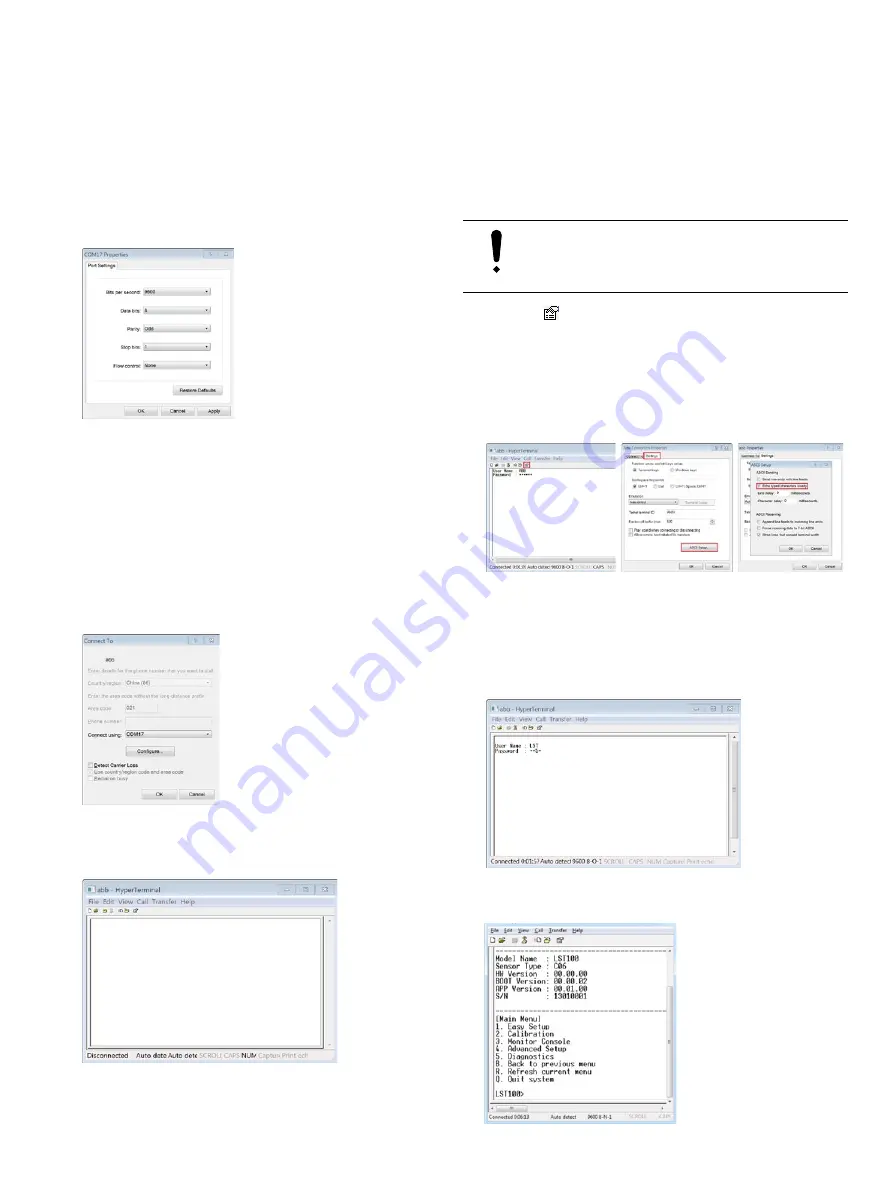
The Com port properties dialog is displayed:

4.  Select the following port settings and click 

OK

.

Bits per second:  9600
Data bits: 

8

Parity: Odd
Stop bits: 

1

Flow control 

None

The Connect To dialog is displayed:

5.  Click 

OK

 to exit connection configuration and return  

to the HyperTerminal window:

IMPORTANT (NOTE)

Step 6 is optional. 

6.  Click the 

 icon (properties) on the top toolbar to  

display the connection properties dialog. Select the  

Settings

 tab and click 

ASCII Setup...

. Check the 

Echo 

typed characters locally

 box and click 

OK

, then  

click 

OK

 again to exit the connection properties dialog.  

Any characters typed in HyperTerminal are now echoed  
for easier visualization of input.

7.  When prompted, input the user name and the password. 

The default logon information is:

User name: 

LST

Password: 5159

Connection to the LST100 is established and the home 
screen of the transmitter is displayed.

Summary of Contents for LST100

Page 1: ...in potentially explosive environments FM approved for use in Zone 2 or Div 2 applications without a barrier or Zone 1 or Div 1 using the recommended intrinsic safety barrier Ultra low power consumption for solar or battery The LST100 has ultra low power consumption equivalent to a 4 to 20 mA instrument functioning constantly at 4 mA Using 1 to 5 V output means low power consumption during all cond...

Page 2: ...t installation using a sleeve 8 3 Electrical connection 9 3 1 Cable connection area 9 3 2 Signal cable connection 10 3 2 1 DC power supply 10 3 2 2 Analog output 10 3 2 3 Digital communications 11 3 2 4 Grounding 11 4 Commissioning 12 4 1 Preliminary checks prior to start up 12 4 2 Preparing for digital communication 12 4 3 Configuring the digital communications 12 4 4 Commissioning the unit 14 4 ...

Page 3: ... measure distance to a liquid surface directly using time of flight through air To measure the level of liquids in tanks indirectly using distance measurement and tank dimensions Using these products as intended involves observing the following points Read and follow the instructions in this manual Observe the technical ratings refer to Section 8 Specifications 1 3 Improper use The following are i...

Page 4: ...RNING indicates a potentially dangerous situation Failure to observe this safety information may result in death or severe injury CAUTION Minor injuries This symbol in conjunction with the signal word CAUTION indicates a potentially dangerous situation Failure to observe this safety information may result in minor or moderate injury The symbol may also be used for property damage warnings NOTICE P...

Page 5: ...t avec un chiffon humide Model No Order No Serial No Temp 40 185 ºF 40 85 ºC Power Supply Measuring Range Protection Class TYPE 4X IP66 67 Date xxxx xx xx LST100 Manufactured by ABB Inc 7051 Industrial Boulevard Bartlesville Oklahoma USA i A B C D E F G H J Certification plate Name plate Fig 1 1 Product labels Name plate A Model number for more detailed information about the technical design refer...

Page 6: ...ements to be taken as the tank approaches empty Use the mounting kit to raise the instrument above the highest point in the tank Close the unit after wiring in order to maintain ingress protection Loosen the cable gland when opening or closing the terminal cover so as not to twist the cable inside the instrument 2 2 Dimensions Dimensions in mm in Ø 77 3 3 0 32 1 3 16 0 6 Ø 40 6 1 6 214 9 8 5 121 9...

Page 7: ... Referring to Fig 2 5 place a seal on the tank surface around the hole and insert the bracket through the seal and the hole Note the seal is used to prevent leakage from the environment into the tank Bracket Seal Fig 2 5 Installing the mounting bracket on a tank with the seal 3 Referring to Fig 2 6 fit a seal over the bottom of the bracket and fit the nut as shown Tighten the nut to secure the bra...

Page 8: ...e LST100 transmitter insert the transmitter through the hole and secure from inside the tank using the nut Fig 2 8 Direct installation using a nut 2 4 2 Direct installation using a sleeve Referring to Fig 2 9 1 Select a sleeve that is compatible with NPT or BSP thread The LST100 transmitter s thread size is 1 5 in for 20 ft version or 2 in for the 30 ft version 2 Fit a seal to the LST100 transmitt...

Page 9: ...tive components LST100 connections have ESD 4 kV protection for contact and 8 kV for air in accordance with IEC 61000 4 ABB strongly recommends using a wrist strap or to discharge electrostatic charge before connecting cables to the LST100 3 1 Cable connection area The electrical wiring is fitted to the LST100 using a 1 2 14 NPT cable gland To ensure the transmitter s NEMA 4X and IP 67 ingress pro...

Page 10: ... LST100 operates from a 12 V DC power supply that is connected to the terminals shown in Fig 3 12 V DC Fig 3 2 12 V DC power supply terminals The power supply voltage is 9 to 16 V DC The minimum power capability of the battery and solar power supply is 120 mW 3 2 2 Analog output LST100 has a 1 to 5 V analog output that is connected using the terminals shown in Fig 3 3 DAC Fig 3 3 Analog output ter...

Page 11: ...baud rate and FM approval requirements The LST100 transmitter s RS485 port is designed for point to point communication and does not support network topology The baud rate of the LST100 transmitter s RS485 communication is fixed at 9600 bps The LST100 supports cable lengths of up to 30 m 100 ft 3 2 4 Grounding The LST100 requires a ground connection to the terminal shown in Fig 3 5 Ground earth Fi...

Page 12: ...Terminal from the flash drive that ships with the LST100 to any convenient location on the computer An RS485 connection to the computer is required for setup but most modern computers are not fitted with RS485 serial communication ports The usual method of establishing an RS485 connection to a modern computer is by means of a readily available RS485 to USB modem The modem s USB plug connects to th...

Page 13: ... is optional 6 Click the icon properties on the top toolbar to display the connection properties dialog Select the Settings tab and click ASCII Setup Check the Echo typed characters locally box and click OK then click OK again to exit the connection properties dialog Any characters typed in HyperTerminal are now echoed for easier visualization of input 7 When prompted input the user name and the p...

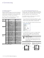
Page 14: ... Reset NO 10 User Password Table 4 1 Factory default settings 4 4 2 Commissioning using the Easy Setup menu The most common configuration parameters are summarized in the Easy Setup menu This menu provides the quickest way to configure the device Use the Easy Setup menu to select dimensions operating mode and engineering units For a detailed description of these menus and parameters see Section 5 ...

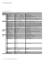
Page 15: ...evel is allowed to change and provides filtering for any brief disturbances 5 Configuration The LST100 uses RS485 communication protocol to enable configuration using a laptop computer 5 1 Menu navigation On the Main menu there are 8 selectable options The first 5 are submenus and the last 3 are navigation options The submenus 1 Easy Setup contains the most important parameters 2 Calibration conta...

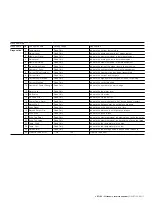
Page 16: ...point 2 short range 5 Actual Value of P2 0 001 to 15 24 m 0 003 to 50 00 ft Actual distance to target for calibration point 2 short range 6 Enable Simulation 1 No Yes Enable Simulation 7 Simulated Voltage 1 to 5800 mV Simulated Voltage used for output calibration 8 Offset of 1000mV 500 to 1500 mV Offset for 1000 mV 9 Offset of 5000mV 4000 to 6000 mV Offset for 5000 mV Monitor Console 1 Level Read ...

Page 17: ...11 Current Blanking Read Only Indicate the curent blanking 12 Number of Power Change Read Only Indicate the number of power change 13 Alarm Level Read Only Indicate the the alarm level 14 NV Status Read Only Indicate the NV statue 15 NV Load Error Read Only Indicate the NV load error 16 Power Down Alarm Read Only Indicate the power shut down but device dosen t restart 17 Almost Full Read Only Indi...

Page 18: ...a known location as a configuration backup or for upload to another device To upload a device configuration 1 Log on to the LST100 using the following logon information User name LSTCONFIG Password 5159 IMPORTANT NOTE The password 5159 is the default user password If the user password has been customized use the updated password 2 Select Transfer in the HyperTerminal toolbar and select Send Text F...

Page 19: ...ar enabling calibration to be performed using only 2 known points This provides sufficient information to calibrate LST100 6 1 Calibration procedure Calibration can be performed on site if the tank dimensions are known This gives best results as it ensures the instrument is calibrated to the intended installation Alternatively the calibration can be performed before installation by pointing the se...

Page 20: ...menu 6 Select 2 Calibration from the main menu Configure the following 4 parameters from the information noted in Steps 4 and 5 Measured value of P1 The measured short range distance noted at Step 4 Actual value of P1 The actual short range distance noted at Step 4 Measured value of P2 The measured long range distance noted at Step 4 Actual value of P2 The actual long range distance noted at Step ...

Page 21: ...ly is below the minimum of 9 V Ensure the power supply voltage is above 9 V 17 Almost Full The distance to the target surface is approaching the Blanking parameter value Measurement has stopped and a Tank Full state is transmitted 5 V 1 Increase the distance to the target surface 2 Increase the value of the Blanking parameter 18 Loss Signal Loss Echo lasts for several minutes 1 Reduce the distance...

Page 22: ...eters monitoring measurement results and diagnostics messages Option for connecting ground 2 terminals as a jumper switch for ground earth Connecting the transducer to ground is optional and is done using this jumper Environmental data Hazardous area approvals Intrinsic Safety type of protection Approval according to FM US and Canada IS Class 1 Div 1 GP ABCD CL II DIV 1 GP EFG CL 1 Zone 1 Non Ince...

Page 23: ...LST100 Ultrasonic level transmitter OI LST100 EN 23 Notes ...

Page 24: ...TX 77042 Ph 1 713 587 8000 3900 South County Road 1290 Odessa TX 79765 Ph 1 432 563 5144 150 Eagle Ford Road Pleasanton TX 78064 Ph 1 830 569 8062 www abb com upstream Note We reserve the right to make technical changes or modify the contents of this document without prior notice With regard to purchase orders the agreed particulars shall prevail ABB does not accept any responsibility whatsoever f...

Reviews: