background image

L ST 3 0 0 |

  CO M PAC T U LT R A S O N I C L E V EL T R A N SM I T T ER  |  L S T 3 0 0 – EN R E V. E

5

1  Introduction

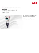
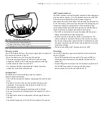
Liquid level measurement has never been easier .

LST300 is the most advanced compact level instrument 
available . With class leading accuracy and specification 
typically only found in expensive remote sensor units, LST300 
changes the way the world looks at compact ultrasonic 
transmitters .

LST300 features high temperature range, corrosion resistant 
design, metal housing, intrinsic safety, advanced diagnostics, 
false echo filtering and even real time on-screen graphic echo 
view . The LST300 can be installed in areas where compact 
instruments were never an option .

LST300 solves many liquid level challenges in liquid storage 
tanks and liquid processes in a wide range of industries, 
including:
•  Water and wastewater
•  Chemical and petrochemical
•  Power
•  Paper and pulp
•  Mining and metals
•  Food and beverage

Summary of Contents for LST300 Series

Page 1: ...ABB MEASUREMENT ANALY TICS OPER ATING INSTRUCTION LST300 Compact ultrasonic level transmitter The most powerful ultrasonic level transmitter in a compact form Measurement made easy...

Page 2: ...stallation requirements 9 Dimensions 9 Direct mounting variations 10 Direct installation using a nut 10 Direct installation using a sleeve 10 Mounting with L shape bracket 11 Mounting with extendable...

Page 3: ...t 34 Menu Process Alarm 35 Menu Communication 35 Menu Diagnostics 36 Menu Calibrate 37 Menu Service 38 Alarm Simulation 38 Device with HART protocol 38 7 Advanced functions 39 Signal waveform 39 Acces...

Page 4: ...ited Zone 2 22 cFMus division 2 Zone 2 22 53 Meter design for NEPSI intrinsic safety ATEX IECEx intrinsic safety Zone 0 20 and cFMus division 1 Zone 0 20 54 Meter design for NEPSI intrinsic safety ATE...

Page 5: ...mpact ultrasonic transmitters LST300 features high temperature range corrosion resistant design metal housing intrinsic safety advanced diagnostics false echo filtering and even real time on screen gr...

Page 6: ...irectly using distance measurement and tank dimensions Using these products as intended involves observing the following points Read and follow the instructions in this manual Observe the technical ra...

Page 7: ...situation potentiellement dangereuse Le non respect de cette consigne de s curit peut entra ner la mort ou des blessures graves WARNING Body injury This symbol in conjunction with the signal word WARN...

Page 8: ...oduct labels for LST300 1 2 3 4 5 6 7 8 9 10 11 12 A B C D 1 Model number 2 Serial number for identification by the manufacturer 3 Order number 4 Power supply 5 Ambient temperature 6 Measuring range 7...

Page 9: ...re ratings The sensor must be installed as perpendicular as possible to the liquid surface being measured Avoid installing the instrument in a location where vibration may be present during operation...

Page 10: ...in hole for U2 process connection into the tank 2 Fit a seal to the LST300 transmitter insert the transmitter through the hole and secure from inside the tank using the nut Figure 4 Direct installati...

Page 11: ...et 350 13 7 Figure 6 Wall mounting with L shape bracket 50 20 60 55 135 180 400 76 370 70 9 290 106 100 17 5 30 100 Figure 7 L shape bracket 350 190 13 7 7 4 Figure 8 Floor mounting with L shape brack...

Page 12: ...REV E Mounting with extendable bracket 547 437 732 17 2 21 5 28 8 Figure 10 Wall mounting with extendable bracket 20 60 76 490 15 9 106 110 50 365 Figure 11 Extendable portion 547 437 732 17 2 21 5 28...

Page 13: ...of holes Diameter of bolt holes Bolt circle diameter C Approximate weight lbs Thread P 3 7 5 0 94 5 4 0 75 6 9 1 5 or 2 NPTF THREAD 4 9 0 0 94 6 19 8 0 75 7 5 17 6 11 1 00 8 5 8 0 88 9 5 26 Table 1 T...

Page 14: ...within the beam angle area Figure 15 INCORRECT CORRECT This is INCORRECT obscuring the KSONIK s line of sight This is CORRECT as obscuring the KSONIK s line of sight Transducer perpendicular to liquid...

Page 15: ...f pipe is needed to max reduce the blanking distance impact or to better adjust to the set up it is recommended to use PE or PVC pipe with a 45degree angle in the end D L Figure 17 NOTICE In case a st...

Page 16: ...touch conductive components LST300 connections have ESD 4 kV protection for contact and 8 kV for air in accordance with IEC 61000 4 2 ABB strongly recommends using a wrist strap or to discharge electr...

Page 17: ...of 21 mA to 22 6 mA The refresh frequency of the 4 to 20 mA output is 0 2 second HART communications The HART protocol is used for digital communication between a process control system PC a handheld...

Page 18: ...6 Cable entry WARNING Explosion proof transmitter must be either repaired by the manufacturer or approved by a certified expert following repair work Observe the relevant safety precautions before dur...

Page 19: ...o the unit 4 Run wiring through the open port Connect the positive lead to the terminal and the negative lead to the terminal IMPORTANT NOTE Do not connect the power across the test terminals which co...

Page 20: ...ter is within temperature limits The transmitter is installed in a location free of vibration The terminal cover is sealed Commissioning using the Easy Setup menu The most common configuration paramet...

Page 21: ...where the tank is empty 6 Configure Span and press Note Span is the distance from the bottom of the tank to the top of the tank In Level mode Span indicates the tank full position 7 Configure Blankin...

Page 22: ...r 4 Marker for indicating relative position within the menu 5 Functions currently assigned to the and control buttons Control buttons Meaning Exit Exit the menu Back Go back to the upper level menu Ca...

Page 23: ...ect the Diagnostics submenu See also chapter 7 Diagnostic Messages Operator Page 1 Select the operator page to be displayed Operator Page 2 Select the operator page to be displayed Operator Page 3 Sel...

Page 24: ...anced level all parameters can be modified The Service menu is reserved to the customer service Passwords can be defined for the Standard and Advanced levels There are no factory default passwords Pas...

Page 25: ...numeric positions using the same procedure as described in steps 3 and 4 7 Press to confirm your setting Exiting the setup Values are mandatory for some menu items Exit a menu without parameter change...

Page 26: ...26 LST300 COMPACT ULTR ASONIC LEVEL TR ANSMITTER LST300 EN REV E...

Page 27: ...LST300 COMPACT ULTR ASONIC LEVEL TR ANSMITTER LST300 EN REV E 27...

Page 28: ...28 LST300 COMPACT ULTR ASONIC LEVEL TR ANSMITTER LST300 EN REV E...

Page 29: ...L TR ANSMITTER LST300 EN REV E 29 1 Distance Alarm Limit and Level Alarm Limit will be displayed based on present PV in Level Mode 2 Distance 100 Distance 0 and Level 100 Level 0 will be displayed bas...

Page 30: ...ly of the configured access level but cannot be changed Menu Parameter Value range Description Device Info Device Device Version Menu Parameter Value range Description Device Info Device Sensor Type C...

Page 31: ...rom sensor to the bottom of the measurement range Span 0 to 12000 mm 50 kHz 0 to 7200 mm 75 kHz Measurement span Blanking 350 to 12000 mm 50 kHz 250 to 7000 mm 75 kHz Distance from sensor where no mea...

Page 32: ...flow measurement Volume Low Alarm Limits 0 to 9999990000 0 m3 Alarm upper limits for volume measurement Volume Low Alarm Limits 0 to 9999990000 0 m3 Alarm lower limits for volume measurement Menu Para...

Page 33: ...be downloaded Contrast 0 to 100 Contrast setting for the LCD display Operator Pages Up to four user specific operator pages layouts can be configured for the process display If several operator pages...

Page 34: ...each line 3rd Line Configure each line 4th Line Configure each line Bar Graph Configure each line Menu Input Output Menu Parameter Value range Description Input Output Current Output Menu Parameter V...

Page 35: ...The output low or high current is set in the subsequent menu Default setting Low Alarm General Alarm is not configurable Low Alarm Max 3 6000 Min 3 5000 Unit mA Select the current for Low Alarm High...

Page 36: ...urement Power Mode Display only The Power Mode of the sensor in the last measurement Power Change Ratio Display only The number of power changes in the last minute Echo Number Display only The number...

Page 37: ...time in second Total Run Time Display only Device total run time in second Reset Interval Time Display only Reset device interval run time Maintenance Time Display only Remaining maintenance time in d...

Page 38: ...nt for level calibration Lower Level Point 0 to 12000 mm Lower level point for level calibration Upper Level Point 0 to 12000 mm Upper level point for level calibration Wet Calibrate Lower Wet calibra...

Page 39: ...re 25 Signal waveform display example 1 Current process values 2 Blanking distance line All signals to the left of this line are ignored 3 Waveform x axis offset Used to scroll along the axis when zoo...

Page 40: ...ighted 2 Press to enter the True Echo Index menu 3 Press to select the position to be changed 4 Press or to scroll through the different process values 5 Press to confirm your selection Changing wavef...

Page 41: ...The True Echo Filtering function is used optimally when obstructions cannot easily be avoided such as submerged pumps and agitators 2 Ensure the tank is empty enough for all obstructions to be visible...

Page 42: ...3 shows echo number 3 is selected as the true echo 9 As an example Echo number 2 is assumed as the desired echo in this step Follow the steps in section Selecting the True Echo Index TEI to change th...

Page 43: ...sy Setup from the main menu 3 Select Volume as the Operate Mode and then press Next 4 Select Empty Distance to configure the distance from the face of the sensor to the bottom of the tank In Level mod...

Page 44: ...onfigure the Volume Unit as required liter is used in this example and then press Next Configure the linearization table 1 Select Calibrate from the main menu 2 Select Linearization from the Calibrate...

Page 45: ...n channel flow function calculates the flowrate in an open channel by measuring level and converting it to a flowrate using standard equations The automated calculation of parameters can only be done...

Page 46: ...lect a value from the Channel Shape box and click Apply The Triangular Notch Thin Plate Weir is selected here as an example 5 The parameters and an image for the selected channel shape are displayed 6...

Page 47: ...shape 9 The linearization table is displayed below 10 Click Store user curve to device to store the linearization table to the device 11 Click Calibration Linearization Linearization to confirm the se...

Page 48: ...xample 5 The parameters and an image for this channel shape are displayed 6 Edit the parameters and click Calculate Max Flowrate 7 The maximum flowrate is calculated and displayed The maximum flowrate...

Page 49: ...before installation by pointing the sensor at a known target There are two kinds of calibration for LST300 One is for wet calibration and the other is for dry calibration Dry calibration Dry calibrati...

Page 50: ...on and the measurement is performed directly from the calibration menu No measurement is required prior to calibration It is however required that the level can be adjusted to the calibration position...

Page 51: ...00 is measuring the lower calibration point by ensuring the conditions as indicated in figure 27 Lower calibration point measured Figure 31 Lower calibration point measured Lower Level Point The actua...

Page 52: ...www abb com level M024 031 Operation Incorrect voltage for device Check power supply Incorrect voltage for proper device operation Check power supply S022 032 Process Environment temperature exceed Me...

Page 53: ...onditions is higher than 60 C at the entry point or 60 C at the branching point of conductors accessories such as cable gland or conductors in conduit with minimum temperature specification of 60 C mu...

Page 54: ...ated conditions is higher than 60 C at the entry point or 60 C at the branching point of conductors accessories such as cable gland or conductors in conduit with minimum temperature specification of 6...

Page 55: ...tection IP66 IP67 If the device is installed as intended this requirement is met by the housing as standard When connected to the line supply the electrical circuits must not exceed overvoltage catego...

Page 56: ...non sparking ATEX IECEx energy limited Zone 2 22 cFMus division 2 Zone 2 22 Certificate of conformity IECEx FME 15 0010X Designation Ex nA IIC T6 T4 Gc Ex tc IIIC T85 C For electrical parameters refer...

Page 57: ...rotected against reversed polarity additional loads enable operation above 42 V DC During use in Exia zones and in other intrinsically safe applications the power supply must not exceed 30 V DC Ripple...

Page 58: ...IIIC T85 C For electrical parameters refer to cert FM15ATEX0064X Ex nA IIC T6 T4 Gc Ex tc IIIC T85 C For electrical parameters refer to cert IECEx FME 15 0010X NEPSI Intrinsic Safety type of protecti...

Page 59: ...LST300 COMPACT ULTR ASONIC LEVEL TR ANSMITTER LST300 EN REV E 59 Note...

Page 60: ...ontained therein Any reproduction disclosure to third parties or utilization of its contents in whole or in parts is forbidden without prior written consent of ABB Copyright 2019 ABB All rights reserv...

Reviews: