CONFIGURATION OF FC610
CONFIGURATION
1TNC928250M0201
48
5
Configuration
5.1
Configuration of FC610
Parameters of FC610 are expected to be configured via HMI panel MP53 or MP56 which is de-
scribed in section 4.
In case of firmware updating or reading event curves, MConfig-G software must be used.
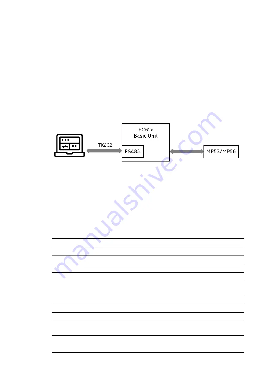
MConfig-G establish communication with FC610 via RS485 communication which is shown be-
low. A dedicated parameterization cable TK202 is required to connect FC610 and the configu-
ration computer with the MConfig-G software installed.
Figure 36: Configuration of FC610
It is also possible to configure FC610 via communication. Please refer to “1TNC928247 FC610
Modbus Protocol Implementation” for more information.
5.2
Factory default setting
For an easy startup of FC610, the following factory settings are preloaded in the device.
Parameters
Range
Factory setting
Feeder Information
Feeder ID
na
System supply voltage
110-50000 V
380 V
Frequency
50/60 Hz
50 Hz
Feeder type
Single phase/3- phase
/3-phase+N
3-phase+N
Feeder power rating
1.5 kW
Feeder nominal current
5 A
Feeder Control
Feedback Function
Current feedback/main switch
feedback*
Current Feedback
External CT Primary
1
External CT Secondary
1


