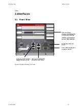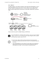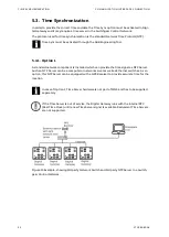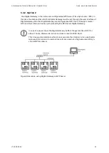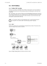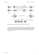
FRONT VIEW
INTERFACES
14
1TGC908004
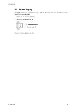
POWER SUPPLY
Button Reset
Reset button (Restart of Digital Gateway)
24V
Power 24VDC
GND
Power Supply 0V
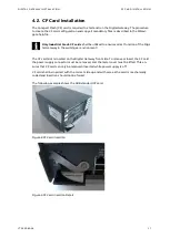
CF CARD
CF Card
CF card is protected against unintentional removal after clos-
ing the flap and connecting the power supply
PORTS
LAN 1
LAN 1 Interface DCS / SCADA (Modbus TCP)
LAN 1 – LED left, green
Link LAN 1 active
LAN 1 – LED right, yellow
Communication Ethernet LAN 1
LAN 2
LAN 2 Interface (Switchgear Control Network)
LAN 2 – LED left, green
Link LAN 2 active
LAN 2 – LED right, yellow
Communication Ethernet LAN 2
LAN 3
LAN 3 Interface (field device connectivity via Modbus TCP)
LAN 3 – LED left, green
Link LAN 3 active
LAN 3 – LED right, yellow
Communication Ethernet LAN 3
USB 1, 2
Not used
Serial 1
Redundancy Interface (male plug)
Serial 2
Modbus RTU Interface (female plug)
LED INDICATIONS
LED 1
Digital Gateway Run indication (CF card application loaded and
running)
LED 2
Digital Gateway Fault
LED 3
Application dependent (see section LED indication, page 60)
LED 4
Application dependent (see section LED indication, page 60)
LED 5
Application dependent (see section LED indication, page 60)
LED 6
DCS Communication active
LED 7
Digital Gateway Power On Indication
LED 8
Application dependent (see section LED indication, page 60) In
redundant configurations: Digital Gateway primary
Table 5 Front View Connectors, LED and Push Buttons
Summary of Contents for LVS Digital
Page 1: ... DISTRIBUTION SOLUTIONS LVS Digital with M10x Motor Controller Interface Manual Modbus ...
Page 6: ......
Page 8: ......
Page 78: ......
Page 80: ... Visit us http www abb com mns Document Number 1TGC908004 M0203 ...


