REDUNDANCY CONFIGURATION
REDUNDANCY
30
1TGC908004
6.2.
Redundancy Configuration
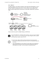
There are three options available to connect DCS or PLC to both Digital Gateway
–
One DCS / PLC Master connected to both Digital Gateway.
–
One DCS / PLC with at least redundant (two) master interfaces
–
Redundant (two) DCS / PLC Master where each is connected to one Digital Gateway
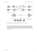
(see example Figure 23/24)
Redundant Digital Gateway connection
Both Digital Gateway
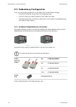
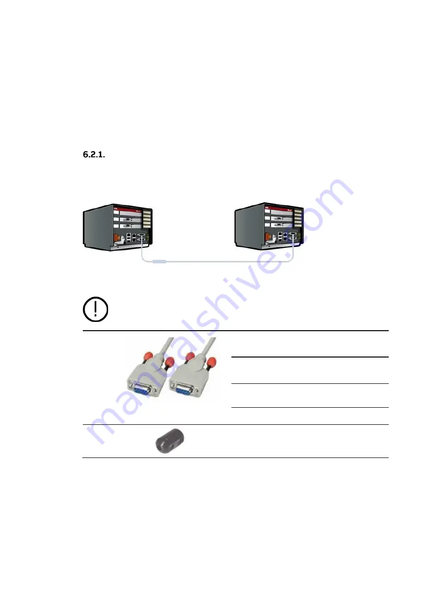
must be connected via a RS232 Null Modem cable (port Serial 1 on both
Digital Gateway) to enable data synchronization and ensure correct operation
Figure 25 Serial 1 to serial 1 redundant link connections with ferrite core
The length of this cable should not exceed 10 meters
Redun-
dant Link
Cables
2m
1TGE120109R0002
3m
1TGE120109R0003
5m
1TGE120109R0005
10 m
1TGE120109R0010
Ferrite
Core
1TGB000197P0001
Table 7 Serial Redundant Link Cable ordering code
Summary of Contents for LVS Digital
Page 1: ... DISTRIBUTION SOLUTIONS LVS Digital with M10x Motor Controller Interface Manual Modbus ...
Page 6: ......
Page 8: ......
Page 78: ......
Page 80: ... Visit us http www abb com mns Document Number 1TGC908004 M0203 ...

