


LIST OF FIGURES
III
—
List of Figures
Figure 2: General LVS Digital System Configuration with M10x-M
....................................................
Figure 3: General LVS Digital System Configuration with M10x-TCP
.................................................
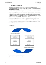
Figure 4 Master Slave Query Response Cycle
........................................................................................
Figure 5 Digital Gateway front view
Figure 6 Power Supply Connector
Figure 7 Digital Gateway Mounting Kit for MNS
...................................................................................
Figure 9 CF Card Insertion Detail
Figure 10 Hardware connection between Digital Gateway and M10x-M
.........................................
Figure 11 Shielding Clamp for RS485
Figure 12 Hardware connection between Digital Gateway and M10x-TCP
.....................................
Figure 13 Digital Gateway directly connected to
..........................................................
Figure 14 Network connection of Digital Gateway and CMES Edge
................................................
Figure 16 Example, using Digital Gateway as NTP Server
..................................................................
Figure 17 Digital Gateway RS232 connection via Serial 2 to DCS
.....................................................
Figure 18 Digital Gateway RS422 connection via Serial 2 to DCS
....................................................
Figure 19 Digital Gateway RS485 connection via Serial 2 to DCS
....................................................
Figure 20 Example for RS485 bus termination and biasing:
............................................................
Figure 21 Digital Gateway Modbus TCP connection with Crossover cable
....................................
Figure 22 Digital Gateway Modbus TCP connection with standard CAT5 cable
Figure 23 Redundant configuration and possible failure scenario – M10x-M
...............................
Figure 24 Redundant configuration and possible failure scenario – M10x-TCP
Figure 25 Serial 1 to serial 1 redundant link connections with ferrite core
...................................
Figure 26 MNavigate IP address Parameterization for Primary and Backup Digital Gateway
Figure 27 MNavigate Fieldbus Slave address Parameterization for Primary and Backup Digital
Gateway
Figure 28 MView Redirecting to Redundant Digital Gateway
...........................................................
Figure 29 Redundancy error shown in MView by a red square
.........................................................
Figure 32 Parameter Window for Serial Switchgear Bus in MNavigate
..........................................
Figure 33 Parameter Window for MODBUS RTU parameters in MNavigate
.................................
Figure 34 Parameter Window for MODBUS TCP parameters in MNavigate
..................................
Summary of Contents for LVS Digital
Page 1: ... DISTRIBUTION SOLUTIONS LVS Digital with M10x Motor Controller Interface Manual Modbus ...
Page 6: ......
Page 8: ......
Page 78: ......
Page 80: ... Visit us http www abb com mns Document Number 1TGC908004 M0203 ...


