background image

ABB-Welcome

  |

— 3 —

Pos: 6 /Busc h-Ja ege r (N eust rukt ur)/ Mo dul-St ruktu r/Onli ne-D oku ment ation /Übe rschri ften  (- -> Für alle D okum ent e < --)/ 1. Eb ene/S  - T /Sicher heit @  18\ mod _13 026 127 917 90_ 15.d ocx @  103 357  @ 1  @ 1

1

Safety

Pos: 7 /Busc h-Ja ege r (N eust rukt ur)/ Mo dul-St ruktu r/Onli ne-D oku ment ation /Sicher heit  (-- > Für alle Dok um ente  <- -)/Wa rn hinweise /Sicher heit  - 23 0 V @  18\m od_ 130 260 681 675 0_15 .docx  @ 1 033 08 @  @ 1

Warning

Electric voltage!

Dangerous currents flow through the body when coming into direct or

indirect contact with live components.

This can result in electric shock, burns or even death.

  Disconnect the mains power supply prior to installation and/or

disassembly!

  Permit work on the 110-240 V supply system to be perf ormed only by

specialist staff!

Pos: 8 /Busc h-Ja ege r (N eust rukt ur)/ Mo dul-St ruktu r/Onli ne-D oku ment ation /Übe rschri ften  (- -> Für alle D okum ent e < --)/ 1. Eb ene/A  - F /Bestim mun gsge mä ßer Geb rau ch @  18\ mod _13 027 6332 131 6_1 5.do cx @  1034 83 @  1 @  1

2

Intended use

Pos: 9 /DinA4  - Anl eitun gen  Online /Inh alt/KNX/Doo rEntry /832 20-AP- xxx/Besti mmu ngsg em aesse r Ge bra uch  - 83 220 -AP-xxx- 500  @ 2 0\mo d_1 324 561 168 699 _15. docx  @ 11 272 8 @   @ 1

This device is an integral part of the ABB-W elcome door communication system and

operates exclusively with components from this system. This device can be mounted

easily inside flush-mounted box.

Pos: 10 /B usch-J aeg er  (Neus truk tur )/M odul -Strukt ur/O nline -Doku me ntatio n/Übe rsch rifte n ( -->  Fü r alle  Doku men te < -- )/1. E bene /U -  Z/U mwelt @  18\ mod _13 026 141 5896 7_1 5.d ocx @  103 383  @ 1 @  1

3

Environment

Pos: 11 /B usch-J aeg er  (Neus truk tur )/M odul -Strukt ur/O nline -Doku me ntatio n/Umw elt ( -->  F ür all e Doku me nte  <-- )/Hinweis e/Hinw eis - U mwelt  - Hinweis  Elektr oge räte  @ 1 8\mo d_1 302 763 973 434 _15. docx  @ 10 350 0 @   @ 1

Consider the protection of the environment!

Used electric and electronic devices must not be disposed of with

domestic waste.

– 

The device contains valuable raw materials which can be recycled.

Therefore, dispose of the device at the appropriate recycling

facility.

Summary of Contents for M2305

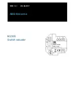
Page 1: ...ABB Welcome Pos 2 DinA4 Anl eitun gen Online Inh alt KNX Doo rEntry 832 20 AP xxx Tit elblat t 832 20 AP xxx ABB 1 9 m od_ 132 3249 806 476 _15 docx 11 108 4 1 M2305 Switch actuator E nde der Liste für Tex tma rke C over ...

Page 2: ...6_1 5 d ocx 109 653 1 1 Safety 3 2 Intended use 3 3 Environment 3 3 1 ABB devices 4 4 Operation 5 4 1 Control elements 5 4 2 Operating modes 6 4 2 1 Call repetition 6 4 2 2 Door opener 7 4 2 3 Time relay 8 5 Technical data 10 6 Mounting Installation 11 6 1 Requirements for the electrician 11 6 2 General installation instructions 12 6 3 Mounting 12 E nde der Liste für Tex tma rke TOC ...

Page 3: ...Geb rau ch 18 mod _13 027 6332 131 6_1 5 do cx 1034 83 1 1 2 Intended use Pos 9 DinA4 Anl eitun gen Online Inh alt KNX Doo rEntry 832 20 AP xxx Besti mmu ngsg em aesse r Ge bra uch 83 220 AP xxx 500 2 0 mo d_1 324 561 168 699 _15 docx 11 272 8 1 This device is an integral part of the ABB Welcome door communication system and operates exclusively with components from this system This device can be ...

Page 4: ...39_ 15 d ocx 110 867 1 All packaging materials and devices from ABB bear the markings and test seals for proper disposal Always dispose of the packaging material and electric devices and their components via an authorized recycling facilities or disposal companies ABB products meet the legal requirements in particular the laws governing electronic and electrical devices and the REACH ordinance EU ...

Page 5: ...0 AP xxx 18 mo d_1 3032 128 536 05_ 15 d ocx 103 673 1 Fig 1 Overview of control buttons No Functions 1 Terminal resistor ON OFF In video installations or audio and video combined installations the switch must be set as RC on on the last device of the line 2 For operating the mode switchover button See chapter Operating Modes 3 Rotary switches for addressing 001 199 4 Bus in out 5 Connection with ...

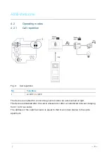
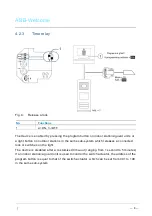
Page 6: ... 220 AP xxx 19 mod _13 1072 339 236 9_1 5 do cx 1 078 41 1 4 2 1 Call repetition Fig 2 Call repetition No Functions 1 2 OFF 3 OFF Pos 74 Di nA4 A nleitu ngen Onlin e In halt KNX Do orEnt ry Bedie nun g M aste r Slave Sc halte r setz en 832 20 AP xxx 1 9 m od_1 310 723 320 966 _15 docx 10 783 3 The device is enabled for an incoming call to control an external bell or light The device is disabled af...

Page 7: ...e r setz en 832 20 AP xxx 1 9 m od_1 310 723 320 966 _15 docx 10 783 3 The device is enabled by pressing the unlock button on indoor stations guard units which releases a connected lock The device is disabled after a customized time out ranging from 1 to 10 seconds The address of the switch actuator is equal to that of an outdoor station in the same sub system 2 3 DIP 1 ...

Page 8: ... system which releases a connected lock or switches on the light The device is disabled after a customized time out ranging from 1 second to 5 minutes If an indoor station a guard unit is used to control the switch actuator the address of the program button is equal to that of the switch actuator which can be set from 001 to 199 in the same sub system Pos 75 B usch J aeg er Neus truk tur M odul St...

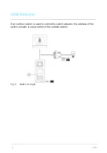
Page 9: ... of the switch actuator is equal to that of the outdoor station Fig 5 Switch on a light Pos 75 B usch J aeg er Neus truk tur M odul Strukt ur O nline Doku me ntatio n Steu er mod ule Onlin e Dok ume ntati on Für alle Dok ume nte S eiten umb ruch 9 m od_ 126 8898 668 093 _0 docx 521 49 1 ...

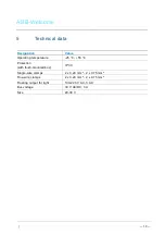
Page 10: ...285 4559 _15 docx 1 037 05 1 Designation Value Operating temperature 25 55 Protection with flush mounted box IP 30 Single wire clamps 2 x 0 28 mm 2 x 0 75 mm Fine wire clamps 2 x 0 28 mm 2 x 0 75 mm Floating output for light 100 240 V AC 3 AX Bus voltage 30 V AC DC 3 A Size 20 30 V Pos 78 B usch J aeg er Neus truk tur M odul Strukt ur O nline Doku me ntatio n Steu er mod ule Onlin e Dok ume ntati ...

Page 11: ...usch J aeg er Neus truk tur M odul Strukt ur O nline Doku me ntatio n Siche rheit Fü r alle D oku ment e War nhinweis e Siche rheit Fachk enn tnisse 18 mo d_1 302 774 384 017_ 15 docx 10 356 4 2 1 6 1 Requirements for the electrician Warning Electric voltage Install the device only if you have the necessary electrical engineering knowledge and experience Incorrect installation endangers your life ...

Page 12: ...lies to avoid interference Do not install the wires of the system bus together with 100 240 V wires Do not use common cables for the connecting wires of the door openers and wires of the system bus Avoid bridges between different cable types Use only two wires for the system bus in a four core or multi core cable When looping never install the incoming and outgoing bus inside the same cable Never ...

Page 13: ...lcome 13 Pos 83 B usch J aeg er Neus truk tur M odul Strukt ur O nline Doku me ntatio n Steu er mod ule Onlin e Dok ume ntati on Für alle Dok ume nte S eiten umb ruch 9 m od_ 126 8898 668 093 _0 docx 521 49 1 ...

Page 14: ...e Ba ckcove r We reserve the right to make technical changes at any time as well as changes in the content of this document without prior notice The detailed specifications agreed to at the time of ordering apply to all orders ABB accepts no responsibility for possible errors or incompleteness in this document We reserve all rights to this document and the topics and illustrations contained therei...

Reviews: