background image

•  Capex and footprint reduction
•  Reduced installation time as all  

the system is pre-tested 

•  Flexibility and scalability with  

full plug-in UPS modules

•  On-premise and cloud base data  

collection and analysis with  
ABB Ability

TM


DISTRIBUTION SOLUTIONS

MNS-Up

Service Manual

Summary of Contents for MNS-Up

Page 1: ...educed installation time as all the system is pre tested Flexibility and scalability with full plug in UPS modules On premise and cloud base data collection and analysis with ABB AbilityTM DISTRIBUTION SOLUTIONS MNS Up Service Manual ...

Page 2: ...egrated low voltage switchgear system comprised of incoming and central manual bypass feeders MNS Up UPS sections and MNS 3 0 outgoing sections The system is based on the well known MNS system in which the MNS Up UPS is integrated ...

Page 3: ...ription 16 05 Packing 18 06 Transport 36 07 Erecting 40 08 MNS Up configuration 48 09 MNS Up Module installation 52 10 Handling of EMC boards 56 11 Communication boards 60 12 MNS 3 0 sections 62 13 Commissioning 64 14 Operating of MNS Up system 66 15 Tightening torques for screw connection 68 16 Spare parts 72 17 Onsite inspection and maintenance 74 18 Maintenance intervals 76 ...

Page 4: ... packing methods 22 5 2 1 The packing for normal road transport 22 5 2 2 The seaworthy packing 23 5 2 3 Horizontal transportation 29 5 2 4 Packaging of switchgear components 30 5 3 Handling of switchgear components 30 5 3 1 Circuit breaker 30 5 3 2 Withdrawable modules 30 5 3 3 MNS Up UPS modules 30 5 3 4 MNS Up Filter modules 31 5 4 Unloading and transport at site 31 5 4 1 Ground transport 31 5 4...

Page 5: ...ent 50 8 3 2 Space covers 51 9 MNS Up Module installation 9 1 Lifting of modules 53 9 2 Adding of module sets 54 9 3 Removing of module sets 54 10 Handling of EMC boards 10 1 Replacing EMC boards 57 11 Communication boards 11 Communication boards 61 12 MNS 3 0 sections 12 1 Handling of ACBs 63 12 2 Earthing of transformer generator connection 63 12 3 Central manual bypass 63 13 Commissioning 13 Co...

Page 6: ... 01 Introduction ...

Page 7: ...cated to the MNS Up section hosting the UPS modules for the other cubicles and the UPS modules please refer to dedicated Manuals MNS Installation and maintenance manual 1TGC902040B0201 DPA 500 Operating Manual 04 3275 REV C Introduction ...

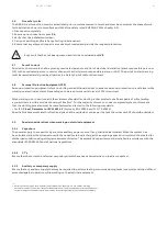
Page 8: ... 02 Safety first ...

Page 9: ...ctors and terminals Electrical energy will follow along the path of least resistance This may include all metallic and conductive components the human body and many fluids Conditions that influence the flow of electrical energy are Intact Insulation Under these conditions the circuit fulfils its designed function and the flow of energy can be predicted Breached Insulation Under these conditions a ...

Page 10: ...fety asset is an alert focused mind Maintain strict discipline regarding safety procedures Use appropriate personnel protection equipment and tools Communicate clearly and ensure all communications are fully understood Query all instructions that are unclear not understood or that appear to be in breach of safety requirements Prove all circuits to be safe if they have been unattended for a period ...

Page 11: ...arc with an incident energy of 8cal cm2 For the majority of work on or near energised systems this means that the clothing provided must be manufactured and tested to the following standards For IEC Class 1 Garments to IEC 61482 1 2 Formerly ENV 50354 and CLC TS 50354 Specific Risk Assesment and Arc Flash analysis shall be carried out and as per the task the minimum PPE should be decided 2 9 Speci...

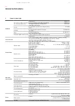
Page 12: ... 03 General technical data ...

Page 13: ...ithstand current Ipk Rated short time withstand current Icw up to 2 000 A up to 220 kA up to 100 kA Arc fault containment Rated operational voltage Prospective short circuit current Duration Criteria IEC TR 61641 up to 690 V up to 100 kA 300 500 ms 1 to 7 Mechanical characteristics Dimensions Sections and frames Recommended height Recommended width Recommended depth Basic grid size ISO 2768 2 200 ...

Page 14: ...ance classification VFI SS 111 Mechanical Dimensions width height depth 1400 x 2200 x 1400 or 1400 x 2200 x 1600 mm mm Mass approx per MNS Up section 500kW system with without 5 modules 1450 950 kg Acoustic noise at 1 m in normal mode at 25 C at 100 load in normal mode at 25 C at 50 load 84 9 av at later stage dBA dBA Safety IEC 62040 1 Access operator restricted Electromagnetic compatibility IEC ...

Page 15: ... 1 For higher ambient temperatures there is a restriction in the operating time in battery mode Mechanical Dimensions width height depth active sub module passive sub module 710 x 178 x 750 mm mm Mass approx active sub module passive sub module 55 54 kg Additional useful information Back feed protection included Color black RAL 9005 General characteristics of filter module Filter module Power rati...

Page 16: ... 04 System description ...

Page 17: ...ut and output neutral conductor 12 Partition wall 3 to main busbar area 4 PE main busbar 13 EMC filter board input line 5 Active MNS Up UPS module 14 EMC filter board output line 6 Passive MNS Up UPS module 15 Multifunction wall 7 MNS Up UPS Filter module 16 Bottom plates 8 Active and passive module compartment 17 Communication interfaces 9 Filter module compartmen ...

Page 18: ... 05 Packing storage and transportation ...

Page 19: ... M10x Energy distirbution Fuse SFU 8E4 upto 24E Contactor feeder Circuit breaker MMS MCCB Contactor feeder Plugin modules Energy distirbution Fuse SFU 6E upto 24E Contactor feeder SlimLine Circuit breaker MMS MCCB Contactor feeder Table 5 01 General overview of standard module solutions customer specific solutions not mentioned If no special instructions are given by the customer packing is carrie...

Page 20: ...ng feeder 4 pole E2 2 upto 2000 A 600 60 350 Incoming feeder 4 pole E2 2 upto 2500 A 800 60 400 Incoming feeder 4 pole E4 2 upto 2500 A 1000 81 500 800 Incoming feeder 4 pole E4 2 upto 4000 A 1000 81 600 800 Incoming feeder 4 pole E6 2 upto 6300 A 1200 143 900 1200 Coupler 4 pole E1 2 upto 1600 A 600 23 300 Coupler 4 pole E2 2 upto 2500 A 800 60 500 Coupler 4 pole E4 2 upto 4000 A 1000 81 600 800 ...

Page 21: ...specification Above mentioned values are only informative should detailed clarification be required please contact your local ABB representative For easy and safe operation withdrawable modules above or equal 12E are equipped with additional side handles Figure 5 01 Module side handle 5 1 1 Container shipment If container shipment transport is needed consider the final packed dimension based on he...

Page 22: ...ons are to be wrapped by plastic film and fixed with the cuplastic strips to the palIets Edges of transport section are protected by standardized edge protection Stripping tape Corner protection Transport section wraped with plastic foil Figure 5 03 Packing for normal road transport Standardized pallets are suitable for handling by forklit trucks To protect them against moisture the switchgear sec...

Page 23: ...length up to 2500 mm 4 wooden beams Box packing length up to 3400 mm 5 wooden beams 2 Side walls Support beams 23 100 mm Side wall panels OSB 3 thickness 12 mm 3 Top Support beams 23 100 mm Top wall panel OSB 3 thickness 12 mm Kartonplast between Support beams and top wall panel 4 Additions Inner AL foil with drying agent Inside dimensions A Lenght B Width C Hight Number of beams A 800 mm 2 Beam 1...

Page 24: ...stack HT IPPC Figure 5 05 Transport marking All sawn wood shall be thermal treated according ISPM 15 standard 1 On the base a 2 mm miralon layer is placed and aluminium foil on top of it Wooden boards and strips are placed on top of this AL foil 2 Switchgear shipping section is placed on those wooden boards ...

Page 25: ... additional packing Figure 5 06 Seaworthy packing procedure steps 1 2 3 4 Unit is secured by placing wooden beams 5 5 cm right around the unit and secured to bottom platform against shifting When two shipping sections placed back to back into one wooden box fiber board 3 5 mm shall be used in between sections ...

Page 26: ...g agent is required for seaworthy packing A single packet 32 DIN is required per 3 m2 box Figure 5 07 Seaworthy packing procedure steps 4 5 6 The shipping section is sealed in AL foil and the air is extracted The unit is then wrapped by plastic film to strengthen the wrap 30 50 40 AL foil Location of humidity detector Transport section wraped with plastic foil ...

Page 27: ...ORTATION 7 Wooden box assembly and execution of aperture for humidity detector verification 30 50 40 8 Shipping unit preparation from the top by wooden beams 5 5 cm against movement Figure 5 08 Seaworthy packing procedure steps 6 7 8 ...

Page 28: ...shall be wrapped with foil after upholstering sharp edges and corners The joints of the foil shall be sealed A protective drying agent according DIN 55474 shall be utilised between the foil and the switchgear No direct contact of this protective drying agent with the switchgear is allowed Only remove the packaging after delivery of the switchgear to site Only remove the transport frames from the s...

Page 29: ...so withdrawable modules shall be withdrawn and transported separately See also in chapter 3 2 4 Packaging of switchgear components As the sections will be moved from horizontal to vertical position on site manually special safety measures has to be taken to have less weight as possible To avoid the deformation of vertical MNS profiles as well also the door hinge a provisory transportation brace sh...

Page 30: ...tyrene corrugated cardboard foil expanded polystyrene board cardboards Any special shipping requirements of the switchgear shipment shall be specified in the ordering phase 5 3 Handling of switchgear components 5 3 1 Circuit breaker Circuit breaker shall be handled in the following way Fixed circuit breaker shall be braced additionally All withdrawable air circuit breakers and withdrawable moulded...

Page 31: ...eams must be removed only for sections with transverse sections up to 1200 kg see Figure 3 14 Switchgear sections could be transported in the vertical or horizontal position see also chapeter 3 2 3 Tilting and canting must be avoided see Figure 3 15 Single sections sections without withdrawable modules circuit breaker sections without circuit breakers may be briefly tilted into the horizontal posi...

Page 32: ...s are equipped with lifting angles see Figure 3 15 Fastening of any Iifting device directly to the frame sections is not permitted The lifting rope angle at the crane hook must not be larger than 120 see Figure 3 16 The lifting angles may be removed after the switchgear has been erected The fastening holes for the lifting angles are to be plugged with plugs if removing the lifting angles see 4 13 ...

Page 33: ...r a rope angle of 90 the permissible load is approximately 40 larger than the values given in the table The arrangements of the lifting angles are shown in Figure 3 15 Shipping units with one or two cubicIes are equipped with single angles Shipping units consisting of three or four sections are equipped with dual angIes The sign detailing the tilting danger must not be removed before all sections ...

Page 34: ...dependent on the type of packaging Sections in standard packaging Store indoor after arrival where no condensation can occur Unpack immediately Open the doors for several hours to acclimatize the equipment Cover the sections with plastic sheeting for any subsequent storage periods Check regularIy for condensation forming under the sheeting prior to the start of installation Sections with export se...

Page 35: ...al conditions like ambient temperature and humidity pollution degree and altitude must be specified during project phase Acc IEC 61439 1 the standard environmental conditions are Ambient air temperature The air temperature does not exceed 40 C and it s average over a period of 24 hours does not exceed 35 C The lower limit of the ambient air temperature is 5 C Humidity conditions The relative humid...

Page 36: ... 06 Transport ...

Page 37: ...site does not allow upright transport 6 1 1 Rolling transport Rolling transport of shipping sections up to 1200kg in weight with min 3 rollers is possible In case of higher weight the transport must be done with a forklift Figure 6 01 Rolling transport 6 1 2 Forklift transport The transport pallets are supported with cross beams to allow the transport with a forklift or hand lift truck Sections ma...

Page 38: ...amp ropes DlN 83325 kg Perlon ropes DlN 83330 kg Steel ropes DlN 15060 160 kg mm2 kg 8 890 10 180 400 1440 12 280 600 2100 14 350 820 2900 16 470 1060 18 580 1340 20 720 1660 24 1000 2400 30 1600 36 2400 For a rope angle of 90 the permissible load is approximately 40 larger than the values given in the table Shipping units with one or two sections are equipped with single angles Shipping units con...

Page 39: ...cuit breaker and withdrawable molded case circuit breaker with rated current of more than 1000 A must be removed and packed separately in their original packaging Heavy busbar constructions must be supported during transport in an adequate way It is important to attach a caution label requiring the removal of the used transport fixing material during switchgear erection Separately shipped circuit ...

Page 40: ... 07 Erecting ...

Page 41: ...een 5 40 C 7 1 2 Floor cutouts In case of cable connection from bottom the following floor cut outs need to be provided The holes in the gland plates need to be prepared on site based on the number and cross section of the cables used 50 100 800 1400 1600 500 600 800 Figure 7 01 Floor cut outs for MNS Up ups section Floor cut outs for other MNS 3 0 sections shall be done as described in the MNS Se...

Page 42: ... ance of at least 100 cm above the MNS Up UPS section 80 150 mm 80 150 mm 1000 mm Figure 7 02 Clearance above MNS Up system 7 3 Clearance behind MNS Up system clearance in front of the section Clearance around MNS Up sections must be Clearance to front min 1000 mm Clearance to left side walls min 80 mm Clearance to right side walls min 150 mm Clearance to back wall min 80 mm 80 150 mm 80 150 mm 80...

Page 43: ... distance of 225 mm and no additional EMC seals are required 7 4 2 EMC seals for shipping splits UPS sections shall be joined with partition wall 19 between two MNS Up sections as well as between MNS Up section and MNS sections EMC sealing needs to be provided on both sides of the partition wall 19 at top and bottom 7 4 3 Rear walls and side walls Rear walls and side walls are unpainted on the ins...

Page 44: ...lit is granted in the filter section of the MNS Up section To get access to the shipping split all filter modules and partition wall 3 need to be removed Main busbar and PE busbar connections shall be done as described in the MNS Service Manual After connecting the main busbars partition wall 3 must be installed and fixed with all screws Figure 7 06 Access to main busbar area reove partition wall ...

Page 45: ...efer to section 13 of this document See MNS service manual for the right torques for the busbar and pe bar joints After joining the main busbars the partition wall must be reinstalled and correctly fixed The PE busbar is located in the front of the MNS Up sections The connection at shipping sections must be done according to the MNS service manual ...

Page 46: ...les are installed in the filter section 7 6 1 Individual batteries Battery connection bars are provided for each module level Figure 7 09 Individual battery connection 7 6 2 Common batteries In case a common battery set must be connected to one MNS Up section the battery connection bars of the different mod ule levels need to be connected using copper links Figure 7 10 Common battery connection ...

Page 47: ...47 ERECTING ...

Page 48: ... 08 MNS Up configuration ...

Page 49: ...00kw installed Figure 8 02 Single section 2 modules in parallel 200kw installed Please check DPA500 user manual section 2 5 8 2 Multiple MNS Up UPS section configuration Multiple section configuration is possible for up to 6 sections with a maximum of 30 modules in parallel Each of the sections can be equipped with 1 5 modules Multiple section systems require Min 2 MNS Up sections Each section sha...

Page 50: ...ve passive and filter module placing 8 3 1 Module arrangement The MNS Up module sets must be installed from bottom to top One module set consists of Passive module Active module Filter module kg The compartment of active and passive modules is mechanically coded to prevent wrong placement of active and passive modules ...

Page 51: ...s Empty space compartments of active passive and filter modules must be closed using the respective space covers Figure 8 04 Space cover active passive module combination Figure 8 05 Space cover active passive module combination 1TGB100370r0101 ...

Page 52: ... 09 MNS Up Module installation ...

Page 53: ...les Wheelchair lifts are recommended for lifting modules up or down Model NEWBINGO 100 height 2000 mm with shelf mounted over the forks Manufacturer supplier LEVANTE Srl Via dell economia 10 46035 Ostiglia Mantova Tel 0039 0386801814 Web www levantelift com Figure 9 01 Forklift ...

Page 54: ...swappable definition but is recommended Remove the active and passive module space covers Install the passive module first Install active module kg Install filter module Follow the start up procedure as described in the DPA500 user manual section 5 15 2 2 9 3 Removing of module sets Turn down the MNS Up module as described in the DPA500 manual 6 11 Disconnect and pull the filter module to isolate ...

Page 55: ...55 MNS UP MODULE INSTALL ATION ...

Page 56: ... 10 Handling of EMC boards ...

Page 57: ...own the MNS Up module as described in the DPA500 manual section 6 11 Open and padlock all filter module breakers Switch OFF and padlock incoming feeders and bypass feeder to completely isolate the MNS Up system Open remote and padlock battery breakers to isolate the battery connections Check that all connections are voltage free Earthing of incoming feeder Earthing of remote battery breaker Remove...

Page 58: ...58 MNS UP SERVICE MANUAL Figure 10 02 EMC board access in MNS Up filter section Reassemble in the opposite way Follow the start up procedure as described in the DPA500 user manual section 6 7 ...

Page 59: ...59 HANDLING OF EMC BOARDS ...

Page 60: ... 11 Communication boards ...

Page 61: ...nection 5 2 LED s green red LED showing the status of the interface board 6 JR3 Graphical display connection 7 SW2 DIP SWITCH for multidrop configuration 8 JR2 RJ 45 multidrop connection multi cabinet configuration 9 X3 UPS inputs and 12VDC source X3 5 6 10 X2 UPS outputs dry ports potential free contacts 11 X1 Interlock function 12 SW1 9 Multi cabinet configuration switch see 5 1 6 and 6 1 2 4 13...

Page 62: ... 12 MNS 3 0 sections ...

Page 63: ...earthing means must be provided in all ACB sections as shown below GS AC AC DC DC Central manual Bypass Distribu on Feeders protected Distribu on Feeders Non UPS proteced Output line Input line Gen Incomer Generator Main Incomer Transformer Ba ery line Ba ery Main Distribu on Feeder AC AC DC DC AC AC DC DC AC AC DC DC AC AC DC DC Figure 12 01 Earthing means for safe maintenance In case of maintena...

Page 64: ... 13 Commissioning ...

Page 65: ...mmissioning procedure as described in the MNS service manual 1TGC902040B0201 section 5 Exception While performing the insulation test on the main busbar system the fuses of the EMC boards have to be disconnected Follow the start up procedure as described in the DPA 500 user manual section 6 7 ...

Page 66: ... 14 Operating of MNS Up system ...

Page 67: ...ONCEPTPOWER_DPA_500kW_EN_REV C 14 2 Handling operating ACBs For operating and maintenance on acbs check the respective service manuals supplied with the system 14 3 Other electrical devices User manuals are supplied for all electrical devices with the MNS Up documentation package For operating and maintenance on any additional electrical device please refer to the respective service manuals suppli...

Page 68: ... 15 Tightening torques for screw connection in MNS Up ...

Page 69: ... material Screw type and ident no Dimensions Thermoplastics and duroplastics PUR Thermoplastics and duroplastics PUR mm Set value nominal Nm Max value Nm Set value nominal Nm Max value Nm TORX pan head tapping screws 1TGB 000 116 P and 1TGB 000 117 P 4 2 1 7 2 0 5 5 3 8 4 5 3 0 3 5 6 3 4 7 5 5 3 0 3 5 Do not exceed max Tightening torques ...

Page 70: ...m Nm Nm mm Nm Nm TORX pan head thread rolling screws 9ADA 629 TORX countersunk head thread rolling screws 9ADA 633 Cheese head thread rolling screws GILN 100 082 P TORX pan head thread rolling screws 1TGB 000 118 P Hex head thread rolling screws GZN 490 181 P Cross recess pan head rolling screws 1TGB 000 002 P Cross recess pan head rolling screws 1TGB 000 003 P Hex head thread rolling screws 1TSA ...

Page 71: ...ghtening torques Set value nominal Max value Nm Nm Hex socket head cap screws DIN00912 with ESLOK GILN 200 124 P Hex head bolts DIN00931 with ESLOK GILN 200 123 P Hex head screws DIN00933 with ESLOK GILN 200 125 P Hex socket head cap screws ISO4762 9ADA 183 Hex head bolts ISO4014 9ADA 56 Hex head screws ISO4017 9ADA 120 M6 6 8 8 M8 17 20 M10 34 40 M12 60 70 M16 119 140 Do not exceed max Tightening...

Page 72: ... 16 Spare parts ...

Page 73: ...bient temperature module 3 MNS Up filter module 1TGB100355R0001 4 MNS Up EMC filter module 1TGB100363R1000 5 MNS Up communication boards Parallel adapter boards SNMP board Profibus card 04 3862 04 3862 04 0594 6 MNS Up HMI 04 2939 7 Battery bar links For later connection of battery bars to allow group or common battery 8 EMC sealing for doors 1TSA383011P0001 9 EMC sealing for enclosure parts 1TSA3...

Page 74: ... 17 Onsite inspection and maintenance ...

Page 75: ... ONSITE INSPECTION AND MAINTENANCE Onsite inspection and maintenance Please refer to MNS Service Manual 1TGC902040B0201 section 7 and maintenance instructions as described in the DPA500 manual section 7 2 ...

Page 76: ... 18 Maintenance intervals ...

Page 77: ... or Tmax Notes on the inspection lists on the following pages The frequency refers to time intervals monthly annually etc service hours starting frequency etc The following abbreviations are used to denote the frequency m monthly a annually n insertion cycles of modules x test in the event of a fault e g after a short circuit Installation category column A distinction is made between the following...

Page 78: ...ules in the section operating or isolated position Cable equipment compartment doors closed open Escape route 650 mm Escape route 650 mm 1a 6m 1a 1a 6m 6m 6m 6m X X X X Unpleasant smell Auxiliary heating possibly required Touch fronts with hand surface check section if hand warm spots are found 1 2 1 2 1 1 2 2 1 2 3 Completion of the interior Equipment compartment Check filling factor and equipmen...

Page 79: ...ce with circuit diagram See Conceptpower DPA500 manual 2a 2a 2a 2a 6m 1a 1a 1a 1a 6m X X X X 6m Measure the insulation resistance For the complete maintenance work observe the instructions of the equipment manufacturer Cf equipment manufacturer Control connection cable 2 0 2 1 1 Withdrawable technique Compact modules 6E 4 6E 2 8E 4 8E 2 Check easy movement of module in compartment Function test of...

Page 80: ... inspection 2 3 Direct connection incoming and outgoing feeders with circuit breaker Additional checks Check main switching device Check current trans former arrangement Check supports at angle and connection sets Condition of parti tioning if available Check external connections Visual inspection of main connections Color change at switch main connections Condition of main and eroded contacts Fun...

Page 81: ...81 MAINTENANCE INTERVALS ...

Page 82: ...cept any responsibility whatsoever for potential errors or possible lack of information in this document We reserve all rights in this document and in the subject matter and illustra tions contained therein Any reproduc tion disclosure to third parties or utilization of its contents in whole or in parts is forbidden without prior written consent of ABB Copyright 2021 ABB All rights reserved Specif...

Page 83: ......

Page 84: ...lutions Electrification business Publication Editor ABB Schweiz Lenzburg Switzerland Local Contacts on abb com mns Copyright 2021 ABB All rights reserved Specifications subject to change without notice 1TGC902050M0202 06 2021 ...

Reviews: