background image


Opis techniczny 


Technical Description


1


MNS DTR / MNS Service 

14 


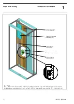
Rys. 6 / Fig. 6 
Szyny rozdzielcze zamontowane w ścianie wielofunkcyjnej (MFS) z zestawami do przyłączeń kabli odpływowych i osłonami szyn 2E 
Cubicle distribution bar embedded in multi-function separator (MFS) with outgoing cable connection unit and 2E distribution bar covers 


Osłona szyn dystrybucyjnych  
Distribution bar cover 

Uchwyt zestawu zacisków kablow. 
Bracket for cable connection unit 

Ściana wielofunkc.  MFS 
Multi function separator 

Zestaw zacisków kabl. 
Cable connection unit 

Szczegół A 

Szyny dystrybucyjne 
Distribution bars 

Summary of Contents for MNS

Page 1: ...MNS Rozdzielnica niskiego napięcia Dokumentacja Techniczno Ruchowa Service Manual ...

Page 2: ...yfikacji Uwaga Wszystkie dane i rozwiązania wskazane w tym dokumencie mogą podlegać modyfikacjom będącymi wynikiem rozwoju produktu Consequences in the event of non compliance ABB shall not assume any liability for any of the following events Negligent handling of the low voltage switchgear system and non compliance with the safety and working regulations as amended from time to time Insufficient ...

Page 3: ... MNS DTR MNS Service 3 Dokumentacja Techniczno Ruchowa Manual Service Montaż uruchomienie obsługa i konserwacja Erection Commissioning Operation and Maintenance Numer dokumentu Publication No 1TGC 902006 M0403 Wydanie Edition 2013 ...

Page 4: ...suwanie ramy transportowej Removal of the transport frame 37 3 4 Posadowienie Erection 38 3 5 Sposoby mocowania do fundamentu Fastening methods to foundation 43 3 6 Podłączenie kabli i przewodów Cable connections wiring 45 3 7 Podłączenie przewodu ochronnego Protective conductor connection 52 3 8 Podłączenie przewodu neutralnego Neutral conductor connection 52 3 9 Informacje dodatkowe Special info...

Page 5: ...tyków siłowych w modułach Installation of power contacts 85 5 9 Uszkodzenia powierzchni lakierniczych Paintwork damage 87 5 10 Uszkodzenia mechaniczne Mechanical damage 87 5 11 Części zapasowe Spare parts 88 5 12 Przybory do drobnych napraw Accessories 91 5 13 Lista zamówieniowa śrub pokrytych środkiem ESLOK List of standard screws with ESLOK threadlocking 92 5 14 Momenty dokręcający połączeń śrub...

Page 6: ...wsporcze Wysokość Szerokość Głębokość Wymiar podstawowy DIN 41488 2200 mm 400 600 800 1000 1200 mm 400 600 800 1000 1200 mm E 25 mm DIN 43660 Ochrona powierzchni malowanie Konstrukcje wsporcze Osłony wewnętrzne Osłony zewnętrzne Pokryte cynkiem lub alucynkiem Pokryte cynkiem lub alucynkiem Pokryte cynkiem lub alucynkiem oraz powle kane farbą proszkową kolor RAL 7035 ja snoszary Stopień ochrony Zab...

Page 7: ...echanical character istics Dimensions Cubicles and frames Recommended height Recommended width Recommended depth Basic grid size DIN 41488 2200 mm 400 600 800 1000 1200 mm 400 600 800 1000 1200 mm E 25 mm acc to DIN 43660 Surface protection Frame Internal subdivision Enclosure Zinc or Alu zinc coated Zinc or Alu zinc coated Zinc or Alu zinc coated and Powder coated RAL 7035 light grey Degrees of p...

Page 8: ...d screws M10 x 18 Depending on the type of construction the cubicle may be enclosed partially or on all sides Doors front covers and rear walls can be provided with ventilation louvers Windows in the doors are made of multilayer safety glass or polycarbonate Depending on the requirements or the design the cubicles are divi ded into functional compartments W przedziale aparatowym instalowane są mod...

Page 9: ...mków Parallel coupling Ściana boczna End plate Wkręt samogwint M6x10 Self tapp screw M6x10 Ściana tylna 5 Rear plate Uchwyt transp Transport lug Dach 7 Roof plate Rys 2 Fig 2 Wyposażenie montowane od przodu przykład Front mounted equipment example Osłona z kratką wentyla cyjną Cover with ventilation louvers Drzwi modułu Module door Moduły wysuwne rozmiaru 8E 4 i 8E Withdrawable module size 8E 4 an...

Page 10: ... MSW patrz Rys 7 Jeśli użyta jest jedna z wymienionych ścian wie lofunkcyjnych to miejsca przeznaczone do wprowadzania sty ków modułów są osłonięte i zapewniają stopień ochrony IP20 Moduły wysuwne są umieszczone w ścianie wielofunkcyjnej MFS wykonanej z materiału izolacyjnego stopień ochrony IP 20 który utrzymuje je w miejscu oraz chroni przed przepię ciami dzięki zastosowanym osłonom szyn Jako al...

Page 11: ...ce 11 Rys 3 Fig 3 System szyn 4 polowy Busbar system with outlined 4th pole Wspornik szynowy 3 lub 4 polowy Busbar support 3 or 4 pole Płytka dociskowa szyn Busbar holding plate Szyny zbiorcze Busbar Płytka dociskowa szyn Busbar holding plate Szyna N N busbar ...

Page 12: ... neutralne N Protective bars PE and neutral bars N Wspornik szyn 4 polowy 4 pole busbar support Szyna N N busbar Szyna PE PEN PE PEN connection bar Szyna N pionowa N connection bar Izolator szyny N 25 N bus insulator Połączenie szyn PE PEN 26 PE PEN connection Szyna N N bar Szyna PE PEN PE PEN busbar ...

Page 13: ...lder Wspornik szyna rozdzielczej Distribution bar holder Tulejka miedziana Busbar connector Płaska szyna dystrybucyjna Flat distribution bar Uchwyt szyny dystrybucyjnej Distribution bar carrier Płytka dociskowa Threaded plate Łącznik kątowy Connecting angle Łącznik kątowy szyny N N connecting angle Rysunek pokazuje kątowe szyny rozdzielcze w górnej części oraz szyny rozdzielcze płaskie w części do...

Page 14: ...yn 2E Cubicle distribution bar embedded in multi function separator MFS with outgoing cable connection unit and 2E distribution bar covers Osłona szyn dystrybucyjnych Distribution bar cover Uchwyt zestawu zacisków kablow Bracket for cable connection unit Ściana wielofunkc MFS Multi function separator Zestaw zacisków kabl Cable connection unit Szczegół A Szyny dystrybucyjne Distribution bars ...

Page 15: ...jnej MSW z osłonami szyn Distribution bars embedded in metal separation wall MSW with distribution bar covers Wkręt samogwint M6x10 Pan head tap screw M6x10 Metalowa ściana wielo funkcyjna Metal seperation wall Wkręt samogwint M5x8 Pan head tap screw M5x8 Wkręt samogwintujący M6x10 Pan head tap screw M6x10 Osłona szyn Protective cover ...

Page 16: ...taż kabli odpływowych w celce na odpowiedniej wysokości The protective bar PE is mounted horizontally in the lower front section of the cubicle and is directly connected to the frame Parallel to this the neutral bar N is mounted on insulators The lengths of the bars correspond to the switchgear shipping unit lengths The protective connection bar is arranged vertically in the cable compartment Para...

Page 17: ...hnique fixed technique control modules or control cubicles front modules indicating measuring annunciating operating and control units mounted on the instrument panel of the front cover or the measuring recess 1 4 1 Bezpośrednie podłączenie do szyn 1 4 1 Direct connection to the busbar Wyłącznik powietrzny ACB do 6300 A lub kompaktowy MCCB do 1600 A jest podłączany bezpośrednio do szyn zbiorczych ...

Page 18: ...any boczne lewa i prawa ściany boczne z przepustami dla kabli odpływowych oraz dolna ściana przedziału oddzielająca od siebie moduły patrz Rys 8 Fixed modules motor starters up to 450 kW and feeders up to 800 A are connected to the distribution bars by means of fixed bolt connections The connections are realized by using power cables or fixed bars The degree of protection is IP 20 against the dist...

Page 19: ...czone do umieszczenia gniazd i styków siłowych przez które moduł łączony jest z szynami dystrybucyjnymi Jeżeli nie użyto ścian wielofunkcyjnych to puste przestrzenie pomiędzy modułami odsłaniające tor dystrybucyjny powinny być osłonięte Podłączenie kablowe do modułu może odbyć się przez złączki kablowe lub bezpośrednio do styków łącznika W zależności od indywidualnego rozwiązania w projekcie manew...

Page 20: ...te do dystrybucji energii Wykonania o szero kości przedziału aparatowego 400mm i 600mm Rys 10 2 Wewnętrzne przegrody oddzielające przedział aparatowy od prze działu kablowego forma wygrodzenia 4a Opcja 1 4 4 2 PowerCenter modules PowerCenter modules have the same construction as plug in modules however they are only available as Energy distribution modules with MCCB See fig 10 1 Taking out PowerCe...

Page 21: ...y Technical Description 1 MNS DTR MNS Service 21 Rys 10 3 Fig 10 3 Osłony do fromy 3b 4b Bellow for Form 3b 4b Rys 10 4 Fig 10 4 Skrzynka kablowa do formy 4b Cable box for Form 4b only 1 4 4 3 Disconnectable modules ...

Page 22: ...cal equipment installation is the same as for plug in modules Railable modules may only be operated from inside Modules may be withdrawn with the help of a handle Grundplatte mounting plate Einlage für Typschild und Türübergangsstecker inset for nameplate and door control plug Schraubverbindung zur Verriegelung in Test und Betriebsstellung screw for interlock of module in test and duty condition i...

Page 23: ...skać 32 40 lub 76 zacisków Panel frontowy modułów wysuwnych rozmiaru 8E 4 i 8E 2 jest wykonany z materiałów izolacyjnych i służy on do instalacji apara tury pomiarowej sterowniczej i oznaczeń identyfikacyjnych Withdrawable units comprise the withdrawable module the frame mounted module compartment Standardized sizes are 8E 4 8E 2 4E 6E 8E 12E 16E 20E 24E 36E 40E 44E und 48E E 25 mm Modules 36E con...

Page 24: ...ęt samogwintujący M6x10 Pan head tap screw M6x10 Wkręt samogw M6x10 Pan head tap screw M6x10 Frontowy słupek oddzielajacy 8E 4 8E 2 76 Front post Wkręt samogw M6x20 Pan head tap screw M6x20 Wkręt samogw M6x10 Pan head tap screw M6x10 Hülse Bushing Podkładka B6 4 Washer B6 4 Punkt uziemienia adaptera modułów PE connecttion for condapter Tulejka mosiężna Bushing Podkładka B6 4 Washer B6 4 Blok zacis...

Page 25: ...rtment above Withdrawable module feeder connection to the distribution bar system is done directly via the contact devices of the withdrawable modules Outgoing cables are connected via plug in contacts to the outgoing cable connection unit main circuit and via terminal blocks auxiliary circuit The outgoing cable connection units are fastened directly to the frame A hinged instrument panel made of ...

Page 26: ...nego Empty withdrawable unit 4E without electrical equipment Leiste Strip Seitenteil rechts Right wall side Ściana tylna Rear wall Grundplatte Base plate Panel frontowy 89 Instrument panel Ściana boczna prawa Right wall side Płyta aparatowa Apparatus plate Listwa Strip Ściana boczna lewa Left wall side Płyta bazowa Base plate ...

Page 27: ...echanizmem manewrowym w modułach 4E 24E Withdrawable module door with interlocking for 4E 24E Uchwyt napędu Interlock link Mechanizm napędu Mechanical interlocking unit Uchwyt 83 Handle Rączka napędu Switch handle Zamek Lock Drzwi Front cover Zamek Lock Tabliczka opisowa 84 Name plate carrier ...

Page 28: ...elkami 2 4x5 cm oraz poprzeczkami drewnianymi 8x10 cm do transportu widłowego patrz Rys 18 lub europalety pasków plastikowych drewnianej kraty jeśli konieczna Celki powinny być przymocowane do palety za pomocą pasów plastikowych Każda jednostka transportowa z profilami poprzecznymi i wadze większej niż 1200 kg jest wyposażona w ramę transportową patrz Rys 18 która ma zapobiec wyginaniu się szafy s...

Page 29: ...ame Rama transportowa Belki drewniane 6 x 10 cm Shipping frame Wooden beams 6 x 12 cm Gwoździe wzmacniające belki poprzeczne Shipping frame Nails for fastening of wooden cross beams Gwoździe wzmacniające belki poprzeczne Shipping frame Nails for fastening of wooden cross beams Belki dociskowe Pressure beams Ściana końcowa End wall Ściana boczna Side wall Osłona z belkami poprzecznymi Cover with wo...

Page 30: ...acc DIN 55474 wooden cross beams 8 x 10 cm for fork lift transport elastic packing means as pads As packaging material the following is allowed Plywood 13 mm Cut timber 24 or 30 mm Slot and feather 28 mm The switchgear has to be wrapped with foil after upholstering sharp edges and corners The joints of the foil have to be sealed A protective drying agent according DIN 55474 has to be provided betw...

Page 31: ...owo zabezpieczane Wyłączniki wysuwne oraz kompaktowe o prądzie ponad 630 A powinny być wysunięte z rozdzielnicy i zapakowane osobno Konstrukcje szynowe o dużym ciężarze powinny być zabezpie czone w odpowiedni sposób Jest ściśle wymagane aby elementy wsporcze instalowane na czas transportu posiadały odpowiednie oznaczenia informujące o konieczności usunięcia tych elementów po zainstalowaniu rozdzie...

Page 32: ...one w czasie transportu czterema śrubami patrz Rys 21 22 Uchwyt manewrowy Uchwyt manewrowy na czas transportu może być przymocowany do uchwytów kablowych patrz Rys 23 Modules with a height 11E 31 E should be protected for transport with 2 screws and a screw cage Modules with a height 31 E should be protected for transport with 4 screws and a screw cage see fig 21 22 Service handle The service hand...

Page 33: ...ewniane belki poprzeczne tylko dla celek do 1200 kg patrz Rys 26 Rozdzielnice należy transportować tylko w pozycji pionowej Należy unikać przechylania i skośnego ustawiania celek patrz Rys 24 Pojedyncze celki bez modułów wysuwnych wyłącznikowe bez wyłączników w sytuacjach awaryjnych gdy wysokość otworu drzwiowego na miejscu instalowania uniemożliwia prawidłowego transportu mogą być krótkotrwale tr...

Page 34: ...npacked Rys 28 Fig 28 Transport dźwigowy zestaw w skrzyni Crane transport transport unit in box Rys 29 Fig 29 Rozmieszczenie uchwytów transportowych celki MNS Arrangement of lifting angles plan view of MNS cubicles Rys 30 Fig 30 Narożnik ramy z uchwytem transportowym Frame corner joint with lifting angle Rama transportowa Belki drewniane 6 x 12 cm Transport frame Wooden beam 6 x 12 cm Belka poprze...

Page 35: ...ear has been erected The fastening holes for the lifting angles are to be plugged with plugs GMN 775 502 P18 if removing the lifting angels Guide values for permissible rope loading Rope diam Permissible Ioad for a four rope arrangement Rope angle at crane hook 120 mm Hamp Ropes DlN 83325 kg Perlon Ropes DlN 83330 kg Steel Ropes DlN 15060 160 kg mm2 kg 8 10 12 14 16 18 20 24 30 36 180 280 350 470 ...

Page 36: ... is undamaged For duration of transport and storage from 12 month up to maximum 24 month and or if the possibility to check the status of the drying agent is needed the following can be used instead of heat sealed PE sheeting Heat sealed aluminium compound foil with integrated hygroscope which provides moisture protection for at least 24 months The hygroscope is visible from the outside through a ...

Page 37: ...przeczne wsporniki odpowiadające podziałowi ce lek Należy zapewnić zachowanie właściwych warunków otoczenia oraz odpowiednie oświetlenie i swobodny dostęp do pomieszczenia z roz dzielnicą Przez odpowiednie ogrzewanie zapobiec dużym zmianom temperatury przy wysokiej wilgotności Wyeliminować kondensację pary wodnej To prevent damage being caused by moisture and dirt the following tasks only examples...

Page 38: ... pneumatyczny Momenty dokręcające połączeń śrubowych dla elementów konstruk cyjnych znajdują się w rozdziale 5 14 The erection of the cubicles should be carried out as described in the following 1 The shipping units which are to be erected in one row have to be aligned accurately and checked that they are vertical Doors and panels must not be twisted or stressed The erection can start at the left ...

Page 39: ...tite270 pozo stałości środka muszą być usunięte z tego połączenia gwintu Ponadto w takim przypadku należy koniecznie użyć nowych śrub i nakrętek 5 The busbars as well as the protective and neutral conductor bars have to be bolted at the transport divisions using the connections provided see fig 34 35 Only ESLOK sealed screws together with one conical spring washer each are to be used The connectin...

Page 40: ...g 3 MNS DTR MNS Service 40 Rys 34 Fig 34 Połączenie szyn głównych Busbar connection Rys 35 Fig 35 Połączenie szyn PE N PE N connection Śruby ESLOK ESLOK screw Podkładka stożkowa Conical spring washer Płytka dociskowa szyn 22 23 Busbar holding plate ...

Page 41: ...ć od góry celki do sufitu powinna wynosić co najmniej 500 mm dla celek odpornych na łuk elektryczny patrz Rys 36 The area around the cubicles to be left clear should be at least 80 mm see fig 37 To be able to mount the last right cubicle the distance between the end cubicle and the right wall must be at least 150 mm see fig 37 In case of left mounted doors the minimal distance between the left wal...

Page 42: ...m Cubicles with busbar compart ment Celka z przedziałem szynowym i kablowym doprowadzenie kabli tylko do przedziału kablowego Cubicles with cable and busbar compartment cable entry only to the cable compartment Celka z przedziałem szyno wym dwustronna Cubicles with busbar com partment and two sided oper ation B Szerokość całkowita celki total width T Głębokość całkowita celki total depth T1 100 B1...

Page 43: ...żdej celki dolnymi profilami do po wierzchni podłogi Ze względu na promień gięcia kabla oraz odpo wiedni dostęp zaleca się by minimalna wysokość podłogi wynosiła 500 mm The erection of switchgears having the cable entries at the bottom requires a foundation with an opening or a cable duct The cubicles should preferably be erected on a base frame which is either embedded in the concrete fIoor or re...

Page 44: ...h welding Spawanie po wypoziomowaniu Welding after levelling Górna część podłogi Top of finished floor Szczyt wlewki Top of unfinished floor max 40 max 55 Mocowanie profila poprzecznego rozdzielnicy Fastening on the transverse provile Szczyt wlewki Top of unfinished floor Górna część podłogi Top of finished floor Mocowanie profila poprzecznego rozdzielnicy Fastening on the transverse provile Głębo...

Page 45: ...3 i 45 Circuit breaker and load break switches are equipped with stan dard cable connection sets for cable connection in parallel see fig 42 43 and 45 Rys 42 Fig 42 Przyłącze szynowe kabli maksymalnie 8 kabli Cable connection sets max 8 cables Rys 43 Fig 43 Przyłącze szynowe kabli maksymalnie 12 kabli Cable connection sets max 12 cables W przypadku wysokich prądów 3500 A muszą być użyte szyny kabl...

Page 46: ...ally at the side of the cubicIes and are connected directly to the control terminals of the circuit breaker moduIes or if necessary to the terminaI strips in the control equipment recess 3 6 2 Podłączenie kabli w celkach z przedziałem kablowym 3 6 2 Cable connection in cubicles with cable compartment 1 Kable siłowe i sterownicze są mocowane do wspornika kablowe go szerokość otworu 16 5 mm w przedz...

Page 47: ...nections in control sections and wiring be tween shipping units Kable sterownicze mocowane są z boku w dolnej części celki i prowa dzone do modułów sterowniczych w poziomych korytkach kablowych Przed osadzeniem kabla zaleca się ustalenie jego położenia odpo wiednimi opaskami Kable sterownicze lub przewody sterownicze do połączeń między celkami prowadzone są wzdłuż celki w kanale przewodów sterowni...

Page 48: ... wyłącznika kompaktowego Connection directly to the MCCB with cage clamps FC 2 x 120 2 x 240 mm Moduł wtykowy PowerCenter forma wygro dzenia 3b lub 4b Plug in module PowerCenter Form 3b 4b 3 4 125 Podłącz poprzez końcówki kabl 2 x 10 2 x 95 mm M10 Connection with cable lugs 2 x 10 2 x 95mm M10 3 4 200 Podłącz poprzez końcówki kabl 2 x 10 2 x 150 mm M10 Connection with cable lugs 2 x 10 2 x 150mm M...

Page 49: ...n modules with INSUM Rys 47 Fig 47 Podłączenie kabli do rozłączników z bezpiecznikami typu SR i XR Cable connections for fused load break switch type SR and XR Rys 48 Fig 48 Listwy kablowe I podłączenie kabli w modułach wysuwnych Terminal strips and cable connections for a cubicle with withdrawable module design Złącze napięciowe Voltage tap Przedział aparatury pomiarowej Measuring and equipment c...

Page 50: ...om 8 E 80 Nm 630 A 3 od from 16 E Rys 49 Fig 49 Podłączenie kabli w modułach wysuwnych od 6E Cable connection for withdrawable modules from 6E Śruba M10 lub M12 Hexagon head screw M10 or M12 Podkładka M10 lub M12 Nut M10 or M12 Przyłącze kablowe Cable connection unit Podkładka sprężysta DIN 6796 Spring washer DIN 6796 Pierścień opcja Adapter ring optional Osłona kablowa Bellow shock protection Pod...

Page 51: ...nection unit 8E Pan head rolling screw M6x10 Pan head rolling screw M6x40 1TSA215002P0286 1TGL110046P0011 1TGL110046P0001 9ADA629 54 9ADA629 61 Rys 50 Fig 50 Przyłącze kablowe dla modułów 4E maks 63 A Cable connection unit for 4E modules max 63 A Maksymalny moment dokręcający śrub 3 5 Nm The max tightening torque of the pan head rolling screws is 3 5 Nm Rys 51 Fig 51 1 Montaż wspornika przyłącza k...

Page 52: ...carrying conductor by altering the colours at the ends or employed as regulator earth or as a connector for the shield earth ln all cases protective conductor connections screwed on to painted surfaces should be secured with serrated contact washers Any means of locking the screws is permissible for fastening screwed connections to gaIvanised surfaces No lock washers are required for roundhead scr...

Page 53: ...rukcję producenta Materiały uszczelniające są dostarczane wraz z rozdzielnicą Kable powinny być wprowadzane do rozdzielnic przez dławiki kablowe Depending on the degree of protection measures are required to be taken at the erection site to seal the cubicles For degrees of protection IP X2 or IP 5X the bottom plate covers flanges have to be sealed if not already done at the manufacturers site To s...

Page 54: ...he equipment is appropriately marked Enclosed mounting instructions have to be obeyed Remove any foreign parts such as tools packing material or conductor scraps from the switchgear Clean insulating parts with an anti static cloth Do not use any solvents as for example carbon tetrachloride trichlorethyIene or hydrocarbons Close the doors Slide the withdrawable modules into testing position see cha...

Page 55: ...łówne obwody oddzielnie Skontrolować wyposażenie ochronne i monitorujące pod wzglę dem poprawności odczytu Przestrzegać zasad i norm bezpieczeństwa Switch on control voltage Test the control protection and monitoring equipment and the mechanical and electrical interlocking devices Apply voltage to the busbars insulation test Switch on the main circuits individually Check the indication and measuri...

Page 56: ...wnątrz po otwarciu drzwi modułu Wyciąganie modułów rozłączalnych pod obciąże niem jest zabronione Przed wyjęciem modułu należy wyłączyć moduł Disconnectable modules may only be operated from inside Taking out disconnectable modules under load is not permitted The load should be disconnected before taking out the modules 4 3 3 Moduły wyjmowalne 4 3 3 Railable modules Moduły wyjmowalne mogą być obsł...

Page 57: ...s achieved as follows Switch off main switching device Insert the module handle as described above Lock the module handle to the module Pull out the module up to the first engaged position Lock the module to the guide rail turning module handle toggle counter clockwise Remove the module handle see fig 56 59 Rys 57 Fig 57 Zablokowanie uchwytu serwisowego Locking the service handle when simultaneous...

Page 58: ...gą być zablokowane w pozycjach serwis test i wysuw przez założenie kłódki patrz Rys 60 i 61 Then the module s control circuit can be tested The isolated position is achieved by unplugging the control plug Railable modules can be locked in service position as well as in test and isolated position by means of padlocks see fig 60 and 61 Rys 60 Fig 60 Mechanizm zamykający modułu wyjmowalnego Interlock...

Page 59: ...ka można obserwować dzięki przezroczystej pokrywie Zamek zainstalowany w rozłączniku chroni go przed możliwością otwarcia w przypadku gdy rozłącznik jest w pozycji załączony ON W przypadku użycia rozłącznika bezpiecznikowego SR M jako główny łącznik zasilający należy pamiętać że bezpieczniki mogą być wyciągane w pozycji OFF rozłącznika The LV HRC fused load break switch type XR SR is a three pole ...

Page 60: ...mi W celce Obwody główne są rozłączone obwody sterownicze są załączone WYSUW W celce lub poza celką Obwody główne i sterownicze są rozłączone SERWIS Może być zabloko wany trzema kłód kami Moduł jest wysunięty na 30 mm z celki Obwody główne i sterownicze są rozłączone oraz istnieje przerwa izolacyjna Position of switch Position of module Main and control circuits ON in cubicle All main und control ...

Page 61: ...a Prawidłowe resetowanie modułu może zostać zrealizowane tylko z pomocą odpowiedniej sygnalizacji np użycie lampki lub sygnału dźwiękowego When moulded case circuit breakers are tripped on faults the switch handle is on position ON The function of the circuit breaker can only be re established by a reset Reset the fault by turning the switch handle from the position ON to the OFF position and furt...

Page 62: ...dostęp do oraz aparatury zamoco wanej na panelu Główny łącznik jest załączany przez ręczne pokrętło przełącznik które spełnia rolę blokady mechanicznej i elektrycznej Blokada elek tryczna wyposażona jest w dodatkowe styki 2Z 2R Withdrawable units size 4E up to 48E are built up of sheet steel components which constitute the supporting frame for the electrical components and the contact elements The...

Page 63: ...do bezpiecznego odłączenia obwodów głów nych i sterowniczych konieczne jest wysunięcie kasety do pozycji SERWIS A secure breaking of the maincircuit is achieved in the OFF position due to the isolating characteristics of the used main switch ing devices In addition it is necessary for working at the consumer to achieve a secure isolation of the main and control circuits by moving the withdrawable ...

Page 64: ...zdzielnicy ustawienie modułu w pozycji SERWIS W tej pozycji obwody główne i pomocnicze są odłączone Aby wysunąć moduł dalej należy znowu przełączyć pokrętło do pozycji WYSUW Wówczas moduł może zostać wysunięty dalej Moving of the withdrawable module The withdrawable unit can only be moved if the operating handle is in position MOVE This ensures that it is not possible to move a withdrawable module...

Page 65: ...able unit which should be moved is installed in a high position in the cubicle the safety stop can be released by supporting the withdrawable unit with the right hand from below and releasing the lever with the left hand Afterwards the withdrawable unit can be removed completely from the cubicle Depending on their size withdrawable units have a high weight Therefore the following safety measures h...

Page 66: ...c zastoso wać zapisy w punktach 5 1 1 1 i 5 1 1 2 Odległość celki od ściany pomieszczenia jest nie mniejsza niż 8 cm Celka jest umieszczona pomiędzy innymi celkami The following preconditions are valid for the standard values given under 5 1 1 1 and 5 1 1 2 Cubicle distance from wall at least 8 cm Middle cubicle in multi cubicle arrangement 5 1 1 1 Standardowe wartości dopuszczalnych strat mocy cz...

Page 67: ...s correspond to an air temperature of 60 C below the roof plate of the switchgear cubicle Reduction factors for withdrawable modules size 8E 4 and 8E 2 see next page IP30 IP42 ventilated IP32 IP54 non ventilated Withdrawable technique Plug in disconnectable and railable technique Cubicles without subdivisions energy distribution electronics 0 100 200 300 400 500 600 700 800 900 1000 1100 1200 1300...

Page 68: ...9 325 W 0 79 198 W Rys 73 Fig 73 Współczynnik redukujący dopuszczalne straty mocy w przypadku zastosowania modułów 8E 4 i 8E 2 Reduction factors applicable to the permissible power loss for withdrawable modules size 8E 4 and 8E 2 5 1 2 Możliwość testowania obwodów sterowania modułów wysuwnych 5 1 2 Possibilities for testing the control circuits of withdrawable modules Zaraz po montażu modułu stero...

Page 69: ...dule is pushed back to isolating position and secured by turning the switch handle to isolation position In this position the control circuit is operational but the power circuit is not Thus testing can be carried out without power For further information refer to table hereunder 3 Testing of the control circuit with the help of a test cable The test cable is designed for carrying out the test out...

Page 70: ...wania od napięcia Uziemienie Osłonięcie sąsiadujących części czynnych Odłącz kable odpływowe i przewody sterownicze Usuń śruby mocujące moduł i ostrożnie wyciągnij moduł z celki Jeżeli jest to konieczne puste miejsce po module musi być osło nięte płytami osłaniającymi w razie potrzeby skontaktuj się ze sprzedawcą ABB Instalacja modułów odbywa się analogicznie w odwrotnej kolejności Plug in modules...

Page 71: ...moduł do kon strukcji celki Ostrożne wyjmij moduł za pomocą rączek Instalacja modułów odbywa się analogicznie w odwrotnej kolejności Disconnectable modules The modules can be removed on live systems Proceed as follows to remove a disconnectable module Isolating the module in compliance with the safety rules Detach outgoing cable and disconnect control cables Modules 7E Pull out positioning screws ...

Page 72: ...rzedziału kablowego z instrukcją obsługi modułów wyjmowalnych Open door with service handle and operating instruction Sposób wysunięcia modułu wyjmowalnego Podnieś nieznacznie moduł i wysuwaj go Wysuń moduł z jego miejsca montażu Usuń uchwyt serwisowy Moduł nie może być przenoszony za uchwyt serwisowy Removing a railable module Lift module slightly and pull it out Lift module out totally by grabbi...

Page 73: ...unięcie modułu Removing the module Wkrętak Aby ułatwić połączenie przewodów sterowniczych do jednego z profili frontowych przedziału kablowego zamontowany jest wkrętak patrz Rys 83 Wiring tool In order to facilitate the connection of control cables a wiring tool is available which is fasted to the front C section of the cable compartment see fig 83 Rys 83 Fig 83 Wkrętak Wiring tool ...

Page 74: ...be applied for The multi function separator is arranged between the busbar and the equipment compartment lt covers the complete height and width of the equipment compartment and fullfils the following functions Holding of distribution bars Fastening and covering of distribution bars by means of the distribution bar cover Protection against formation and propagation of arc faults As an alternative ...

Page 75: ... większy kilkoma mniejszymi lub mniejsze jednym większym konieczna jest przebudowa przedziału aparatowego celki odpływo wej patrz Rys 86 87 The withdrawable module can be exchanged or removed and replaced in the compartment during maintenance without isola tion With the interIocking switch handle in the move position with drawable modules size 8E 4 and 8E 2 can be withdrawn without stop The module...

Page 76: ...onversion and or change of with drawable module compartments the withdrawa ble module below the affected withdrawable module compartments has to be removed from the cubicle By using a appropriate cover for the compartment bottom plate of the withdrawable module compartment below small parts have to be prevented from falling through In case of modifications of switchgear cubicles a possible change ...

Page 77: ...fter protective cover bellows has been removed Due to the protective covers on the adjacent cable connection units work inside the cable compartment can be performed without danger see fig 49 Disconnect control wiring Remove control terminal block and its support located at the lower right hand side of the compartment in the cable compartment The left guide rail on the Iower compartment bottom pla...

Page 78: ...zebudowa jest wykonywana w następującej kolejności Demontaż Wyciągnąć 6 modułów 8E 2 Rozłączyć kable zasilające i przewody sterownicze Zdemontować trzy płyty dolne przedziału wraz z prowadnicami i słupkami oddzielającymi patrz Rys 13 Zdemontować 3 adaptery modułów wysuwnych patrz Rys 13 Montaż Zamontować wspornik przyłącza kablowego i na nim przyłącze kablowe szczegóły patrz Rys 50 Typ przyłącza k...

Page 79: ...jest użycie dwóch przyłączy kablowych Montaż Podłączyć kable zasilające z osłonami oraz kable sterownicze patrz Rys 49 Wsunąć nowy moduł 24E W celu zamówienia materiałów niezbędnych do przebudowy celki należy skontaktować się z działem sprzedaży ABB The conversion has to take place in the following sequence Disassembly Pull out the 3 withdrawable units Disconnect power cables after protective cove...

Page 80: ...cem wsunięcia do kondaptera modułów wysuwnych jest lek kie Czy izolacja przewodu nie została zaciśnięta podczas zaciskania styku Czy styki są nasmarowane According to the applicable national and international standards and provisions e g DlN 57 105 part 1 VDE 0105 part 1 BGV A2 electrical plants must be maintained in an orderly condition by their operator For all works in connection with the activ...

Page 81: ...ting system and or informing the respective ABB Service department in order to determine and coordinate further measures Przed sprawdzeniem szyn dystrybucyjnych lub kondapterów modułów wysuwnych wyłącz rozdziel nicę spod napięcia Before checking the distribution bars or the withdrawable module condapters disconnect the cubicle from the power supply Typ styku Contact type Opis Specification applica...

Page 82: ...quisite for reaching the operating cycles to which the unit is certified through type test as the grease reduces the wear of the contact area finish Further more the force needed for withdrawing the modules is reduced Contact areas of the power contacts are to be cleaned and greased whenever the following conditions apply the assembly works and testing routines have been completed in the workshop ...

Page 83: ...400 A 4 contacts each 0 25 tubes over 400 A 4 contacts each 1 tube Prior to transport packaging the appropriate number of tubes has to be fixed to the modules by the manufacturing department tubes are fixed to the withdrawable module handle at least one tube per packaging unit in case of major deliveries to one customer the grease can also be supplied in tins Example 1 module size 8E 250 A 8 conta...

Page 84: ...dules have been in use for some time it may be necessary to lubricate the interlocks of the withdrawable modules size 8E 2 and 8E 4 dependent on the environmental conditions and the tightness For this purpose the mobile parts must be sprayed with a lubricant approx 1 sec Thereafter a functional test must be carried out Lubricant to be used Molycote Omnigliss Spray Liquid high pressure lubricant in...

Page 85: ... gdy styk nie zostanie prawidłowo zainstalowany w zatrzasku należy sprawdzić czy zatrzask ten ma prawidłowy kształt np nie posiada nadlewów i czy nie jest on połamany Tak uszko dzone elementy muszą być wymienione Once inserted in the withdrawable module rear wall 1TGB120050P0001 or the contact housings 1TGB120048P0001 and 1TSA233000P0007 the contact must be properly engaged Successful engagement i...

Page 86: ...alne sprawdzenie nie jest możliwe Dlatego też styki siłowe są odpowiednio oznaczone Na nożach styków znajduje się oznaczenie Ag lub Sn Identification The type of plating is visually not distinguishable That is why contacts are marked on the contact fingers impression of Ag or Sn Połączenie styków o różnych pokryciach powierzchni w jednej rozdzielnicy Dotyczy w szczególności modułów wysuwnych i mod...

Page 87: ...epends on the surface preparation and or the handling 5 10 Uszkodzenia mechaniczne 5 10 Mechanical damage 5 10 1 Przygotowanie uszkodzonego miejsca 5 10 1 Preparation of the damaged Iocation W przypadku zniszczenia dużej powierzchni należy ją przetrzeć pa pierem ściernym gr 400 Następnie uszkodzoną powierzchnię należy przetrzeć szmatką lnianą lub oczyścić sprężonym powietrzem When major damage to ...

Page 88: ... for busbar connection lnsulating angle lnsulator Fastening bracket 1TGL100024R0001 1TGL120007P0001 GZN 560103P0003 GLBS300210P0001 Moduły wtykowe Plug in design Korytko kablowe Uchwyt ze śrubą Uchwyt płytki znamionowej Osłona Wiring duct Cage Name plate carrier Cover for spare spaces 1TGB120026P0460 1TGB120030P0001 1TGB110159P0001 GLBL100032R Płyty montażowe bez otworów montażowych na aparaturę P...

Page 89: ...51A S 1TGB100052A S Przyłącza kablowe Osłona kabli do rozłączników wielkości 00 1 Osłona kabli do rozłączników wielkości 2 3 Zestaw wsporników kablowych Cable connection Bellow size 00 1 Bellow size 2 3 Cable support cpl 1TGB120070P0001 1TGB120071P0001 GLBL100014R Moduły wysuwne Withdrawable design Przedział przeznaczony do instalacji modułu Płyta dolna przedziału Szyna prowadząca moduł 8E 2 i 8E ...

Page 90: ... do mod 8E Styki Ag 4 pol M10 160 A do mod 8E Styki Sn 6 pol M10 160 A do mod 8E Styki Ag 6 pol M10 160 A do mod 8E Styki Sn 3 pol M12 400 A do mod 8E Styki Ag 3 pol M12 400 A do mod 8E Styki Sn 3 pol M12 630 A do mod 16E Styki Ag 3 pol M12 630 A do mod 16E Styki Sn Cable connection units 3 pole 25 mm2 63 A for 4E Ag cont 3 pole 25 mm2 63 A for 4E Sn cont 3 pole M10 250 A for 6E Ag cont 3 pole M10...

Page 91: ...nent paint Shade RAL 7035 Smar do styków siłowych Klüberlectric KR44 102 Contact grease Klüberlectric KR44 102Topas NB 52 Smar wysokociśnieniowy puszka 300 ml Liquid high pressure lubricants Molycote Omnigliss 300 ml tin Cromadex D 71636 Ludwigsburg Niemcy Germany Klüber Lubrication KG D 81379 München Deutschland Germany Dow Corning GmbH D 65201 Wiesbaden Deutschland Germany 1TGB000172R1000 1 kg p...

Page 92: ... 4762 8 8 A G Hexagon head bolt DIN 931 ISO 4014 8 8 A G Hexagon head screw DIN 933 ISO 4017 8 8 A G Hex socket head cap screw DIN 912 ISO 4762 8 8 A G M10 x 50 M10 x 60 M10 x 70 M10 x 80 M12 x 40 M12 x 50 M12 x 60 M12 x 70 M12 x 80 M12 x 90 M12 x 100 M12 x 110 M12 x 120 M12 x 130 M 8 x 25 M10 x 16 M10 x 18 M10 x 20 M10 x 25 M10 x 30 M10 x 35 M10 x 40 M10 x 45 M10 x 50 M10 x 55 M10 x 60 M12 x 30 M...

Page 93: ...ipment when this is made with flat copper terminals and bolts and nuts of tensile class 8 8 Note For equipment connections and mountings see the technical data sheets of the manufacturers 5 14 2 Dokładność dokręcania 5 14 2 Exactness of Screwing Bolting Do dokręcania śrub należy użyć narzędzi o wysokiej dokładności które są dostosowane do ustawienia maksymalnych momentów dokręcających z uwzględnie...

Page 94: ...d thread rolling screws M3 M4 M5 M6 M8 1 5 1 5 1 5 2 0 3 0 1 0 2 0 4 5 5 5 9 5 3 0 3 0 3 0 3 0 3 0 1 0 2 0 4 5 5 5 5 5 5 0 9 5 Jeżeli śruba samogwintująca poluzuje się to jej ponowne dokręcenie nie powinno odbywać się przy użyciu narzędzi mechanicznych Należy użyć wkrętaka Are self tapping and thread rolling screws loos ened then they later be only tightened no more with a machine equipment but wi...

Page 95: ...nie elementy przewodzące przed przy padkowym zetknięciem In the worst case compensation systems are permanently operated with their maximum power Therefore good ventilation is to be en sured in the place of installation in order to prevent the ambient temperature from exceeding the max admissible limit of 35 C mean value over 24 hours Malfunctions or an insufficient compensation power can be best ...

Page 96: ...on of faults W razie wystąpienia usterek w czasie uruchomienia baterii należy sprawdzić połączenia przewodów szczególnie w przedziałach transportowych Inne możliwe usterki wymieniono poniżej Wyświetlacz regulatora jest ciemny Sprawdzić napięcie sterownicze Regulator nie włącza dodatkowych stopni Sprawdzić poprawność podłączenia układu pomiarowego Sprawdzić bezpieczniki Zła przekładnia transformato...

Page 97: ...pomiarowego napięcia zamiana faz lub fazy i zera Małe różnice mogą być wynikiem nieodpowiedniego pomiaru lub różnych punktów pomiaru Too many steps active overcompensation Check transformer installation Check controller settings Wrong measuring voltage connection phase phase and phase N exchanged cos display does not coincide with additional power factor meter reading wrong voltage measuring conne...

Page 98: ...14 R0114 R0114 2 x 3 x 77 6 x 77 6 x 77 116 232 464 18 0 36 1 72 2 1TGR431002R5210 1TGR431002R5220 1TGR431002R5140 500 500 500 R0220 R0021 R0021 R0121 R0121 2 x 3 x 111 6 x 111 6 x 111 Y Y Y 56 111 222 11 5 23 1 46 2 1TGR431002R6210 1TGR431002R6220 1TGR431002R6140 690 690 690 R0222 R0023 R0023 R0123 R0123 2 x 3 x 64 5 6 x 64 5 6 x 64 5 Y Y Y 32 65 129 8 4 16 7 33 5 1TGR431002R6213 1TGR431002R6225 ...

Page 99: ...04 R0104 2 x 3 x 58 6 x 58 6 x 58 87 174 348 14 4 28 9 57 7 1TGR431006R5210 1TGR431006R5220 1TGR431006R5140 500 500 500 R0220 R0021 R0021 R0121 R0121 2 x 3 x 111 6 x 111 6 x 111 Y Y Y 56 111 222 11 5 23 1 46 2 1TGR431006R6210 1TGR431006R6220 1TGR431006R6140 690 690 690 R0201 R0002 R0002 R0102 R0102 2 x 3 x 58 6 x 58 6 x 58 Y Y Y 29 58 116 8 4 16 7 33 5 1TGR431007R4120 400 R0024 R0103 3 x 64 5 3 x ...

Page 100: ...strated by the following equivalent circuit diagram C Rw RD Ru Ri Rt RW rezystancja zastępcza stała RD rezystancja dielektryczna RU rezystancja zależna od napięcia Ri rezystancja zależna od prądu Rt rezystancja zależna od czasu C Rw RD Ru Ri Rt RW constant equivalent resistance RD dielectric resistance RU voltage dependent resistance Ri current dependent resistance Rt time dependent resistance Dla...

Page 101: ...outer conductors Pomiar niewymagany jeśli kabel zawiera linię zerową lub uziemioną osłonę dla wyłączników obwodów oświetleniowych This measurement is not required if the cable includes a grounded conductor or a grounded sheath for switch leads in lighting circuits 4 Pomiar pomiędzy przewodem fazowym a przewodem N Between the outer conductors and the neutral conductor Pomiary mogą być także wykonyw...

Page 102: ...zolacji składa się z wielu czynników składowych które z kolei zależą od innych Powoduje to dużą zmien ność wartości tej rezystancji The operating error within the marked measuring range must not exceed 30 with respect to the value reading This error range permitted by DIN VDE 0413 part 1 initially seems to be very high From the equivalent circuit diagram above however it becomes obvious that the i...

Page 103: ...y Czas przełą czenia współczynnik wyłączony Moduły kompensacyjne Typ R Numer Stopniowanie x kvar A Kondensator Rok produkcji Stopień Pojemność znamionowa µF Pojemność terminalu µF Stopniowanie x kvar Typ R Numer Rok produkcji B Kondensator Stopniowanie x kvar Stopień Pojemność znamionowa µF Pojemność terminalu µF Rok produkcji Pomiary pojemności Pomiary prądu U L1 U L2 U L3 Stopień 1 2 3 4 5 6 7 N...

Page 104: ... R Number Stepping x kvar A Capacitor Manuf year Step Nom capacitance µF Terminal capacitance µF Nom current A Type R Number Stepping x kvar B Capacitor Manuf year Step Nom capacitance µF Terminal capacitance µF Nom current A Capacitance measurement Current measurement U L1 U L2 U L3 Step 1 2 3 4 5 6 7 Setpoint Phase L1 Phase L2 Phase L3 Step 8 9 10 11 12 13 14 Setpoint Phase L1 Phase L2 Phase L3 ...

Page 105: ...ycie powoduje możliwość narażenia na niebezpieczeństwo Aby móc zlokalizować wszystkie usterki które mogą wydarzyć się po zainstalowaniu systemu elektrycznego po naprawie lub modyfikacji zgodnie z normami DIN 57105 część1 oraz VDE 0105 część 1 należy wykonać testy sprawdzające Jednakże normy te nie podają żadnych konkretnych danych na temat cyklu testów Testy sprawdzające służą ocenie prawidłowych ...

Page 106: ...e W przypadku odizolowania systemu należy odczekać jedną minutę w celu rozładowania kondensatorów Dodatkowo należy zewrzeć izolowanym kablem obwód wyjściowy kondensatora Należy sprawdzić czy przekładniki prądowe zostały zwarte przed ich odłączeniem lub załączeniem Kondensator powinien być zainstalowany zgodnie z normą IEC 831 1 2 oraz krajowymi normami Zwarte obwody są zagrożeniem dla życia i apar...

Page 107: ...suwne 2 2 Moduły wtykowe rozłączalne i wyjmowalne 2 3 Szafy zasilające i odpływowe wyposażone w wyłączniki np Emax Isomax lub Tmax 1 General visual inspection repetitive tests 1 1 External inspection 1 2 Completion of the interior 1 3 Switchgear and controlgear assemblies withdrawable or plug in modules 2 Additional inspections 2 1 Withdrawable technique 2 2 Plug in disconnectable railable techniq...

Page 108: ...łony Czystość kratek wentylacyjnych Dach rozdzielnicy zanieczyszczony otwarty uszkodzony itp Zamocowanie drzwi przedziału kablowego osłon tylnych i bocz nych Pozycja modułów wysuwnych w rozdzielnicy stan załączony lub w pozycji testu Drzwi kablowe otwarte zamknięte 1 1 4 Dostęp Droga ucieczki 650 mm 1a 6m X 1 2 Oględziny wnętrza 1 2 1 Przedział aparatowy Sprawdzenie współczynnika jednoczesności Wy...

Page 109: ... 8 Sprawdzenie obwodów pomiarowych Zgodnie ze schematem połączeń 2a 1a X 2 0 Testy dodatkowe 2 1 Moduły wysuwne 2 1 1 Moduły wysuwne 8E 4 i 8E 2 Sprawdzenie swobody przesuwu modułu w przedziale Usunąć kurz i nasmarować prowadnice 2 3a 1a X Sprawdzenie funkcji testowych mechanizmu napędowego Nanieść smar z Omnigliss 2 3a 1a X Sprawdzenie styków elektrycznych 2a1 1a1 X głównych Inspekcja wizualna Pa...

Page 110: ...iernej Sprawdzić wyposażenie elektryczne w każdym module 1a 6m X Oględziny styków głównych X01 Sprawdzenie odstępów styków stanu styków i smarowania nie po trzebne Sprawdzenie ochrony zwarciowej Bezpieczniki NH Stan bezpieczników ciągłość Bezpieczniki wyłączone Sygnały przeciążenia zgodnie z instrukcjami producenta Wyłączniki Stan styków siłowych Smarowanie noży styków bezpieczników Klüberlectric ...

Page 111: ...2 3 Połączenia bezpośrednie szafy zasilające lub odpływowe z wyłącznikami Analogicznie do p 1 3 Dodatkowe sprawdzenia Sprawdzenie wyłącznika głównego Oględziny połączeń głównych 1a 6m X Przebarwienia połączeń głównych Stan styków głównych i pomocniczych Postępować zgodnie z instrukcją producenta Test funkcjonalny 1a 6m X Sprawdzenie instalacji przekładników prądo wych Zamocowanie transformatorów P...

Page 112: ...r dusty covered Roof plate contaminated covered obstructed etc Fastening of cable compartment doors side and back panels Position of withdrawable modules in the cubicle operating or isolated position Cable equipment compartment doors closed open 1 1 4 Accessibility Escape route 650 mm 1a 6m X 1 2 Completion of the interior 1 2 1 Equipment compartment Check filling factor and equipment Arrangement ...

Page 113: ...ance with circuit diagram 2a 1a X Control connection cable 1 3 8 Check measuring loops In accordance with circuit diagram 2a 1a X 2 0 Additional checks 2 1 Withdrawable technique 2 1 1 Compact modules 8E 4 8E 2 Check easy movement of module in compart ment Remove dust and grease from guide rail if necessary 2 3a 1a X Function test of mechanical interlock Lubricate with Omnigliss 2 3a 1a X Check el...

Page 114: ... X Check of contact gaps Visual inspection of main contacts X01 contact condition and Condition of short circuit protection lubrication not neces sary LV HRC fuse Fuse continuity Fuse tripped Signs of overload by mains Circuit breaker Contact condition resonance in accord ance Lubricate contact blades of LV HRC fuses Klüberlectric KR44 102 with manufacturer s Check capacitor contactor instructions...

Page 115: ...2 3 Direct connection incoming and outgoing feeders with circuit breaker Analogous to item 1 3 Gen inspection of switchgear assembly Additional checks Check main switching device Visual inspection of main connections 1 6m X Procedure in Color change at switch main connections accordance with Condition of main and eroded contacts manufacturer s Function test 1a 6m X instructions Check current trans...

Page 116: ......

Page 117: ... dokumentu bez uprzedniego powiadamiania W przypadku zamówień obowiązywać będą uzgodnione warunki ABB Sp z o o nie ponosi żadnej odpowiedzialności za potencjalne błędy lub możliwe braki informacji w tym dokumencie Zastrzegamy wszelkie prawa do niniejszego dokumentu i jego tematyki oraz zawartych w nim zdjęć i ilustracji Jakiekolwiek kopiowanie ujawnianie stronom trzecim lub wykorzystanie jego zawa...

Reviews: