MANUAL MOTOR STARTER GUIDE
APRIL 19
15/80
2.1.3 Overload protection
An overload is defined as an operating condition in an electrically damaged circuit which causes an overcurrent. In
compliance with international and national standards, manual motor starters have a setting scale in amperes, which
allows the device to be adjusted directly without any additional calculation. In compliance with international and na-
tional standards, the setting current is the rated current of the motor and not the tripping current (no tripping at
1.05 x I, tripping at 1.2 x I after 2 hours; I = setting current).
2.1.4 Overload trip classes
ABB manual motor starters fulfill their trip classes in accordance with IEC 60947-4-1 and UL 60947-4-1A. The trip
class of a manual motor starter indicates the maximum tripping time from a cold state. This tripping time refers to a
steady symmetrical three-pole load with a 7.2x current setting.
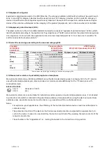
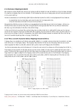
Tripping times in accordance with IEC 60947-4-1 and UL 60947-4-1 can be seen in the figures “Tripping characteris-
tics”.
Class
Tripping time T
p
[s] at 7.2 x I
e
10A
2 < T
p
≤
10
10
4 < T
p
≤
10
20
6 < T
p
≤
20
30
9 < T
p
≤
30
Table 3: The information above is based on IEC 60947-4-1 and is intended for reference only.
2.1.5 Short-circuit protection
A short-circuit is defined as an accidental or intentional conductive path between two or more conductive parts forc-
ing the electrical potential between these conductive parts to be equal to, or close to, zero. The short-circuit release
is set at a fixed multiple value (non-adjustable) of the manual motor starter’s rated operational current I
e
.
The short-circuit releases of the manual motor starter disconnect the load from the grid in each of short-circuits,
thus preventing further damage. With a short-circuit breaking capacity up to 100 kA at a voltage of 400 V AC, the
manual motor starter is considered to be short-circuit proof if higher short-circuit currents are not to be expected at
the installation site of the devices
.
2.1.5.1 Short-circuit coordination
The main task of the short circuit protection device is the rapid detection, limiting and switching off of high fault
currents and limiting the damage to the short circuit location.
If you want to ensure that no components are unduly loaded or damaged by the short circuit current shutdown, mu-
tual coordination of the starter components contactor and circuit-breaker is necessary. The short-circuit
coordination between switching and protection devices covers the electro-physical processes of all components
loaded in the event of a short circuit.
2.1.5.2 Definition according to IEC 60947-4-1
Coordination type 1:
−
In the event of a short circuit, the contactor or the starter must not endanger persons and equipment.
−
The contactor or the starter need not be suitable for further operation without repair and partial renewal.
−
Damage to the contactor and the overload relay is permitted.
Coordination type 2:
−
In the event of a short circuit, the contactor or the starter must not endanger persons and equipment.
−
The contactor or starter must be suitable for further use.
−
The overload relay or other parts must not be damaged, except for the welding of the contactor or starter
contacts, if they are easy to disconnect without appreciable deformation (for example with a screwdriver).
For additional information to select the right short-circuit coordination type, please use the Selected Optimized Coordination (SOC) selec-
tion tool (
http://applications.it.abb.com/SOC/page/selection.aspx

