Start-Up Procedure
5
3. HARDWARE STARTUP
a. CONNECTOR PLATES
There is only one connection between the Spectroradiometer and the computer: a 25 pins serial cable for the
MR100 or an optical fibre cable for the MR200. One end of the data cable connects to the respective connector
plate for each instrument as indicated on the next two figures.
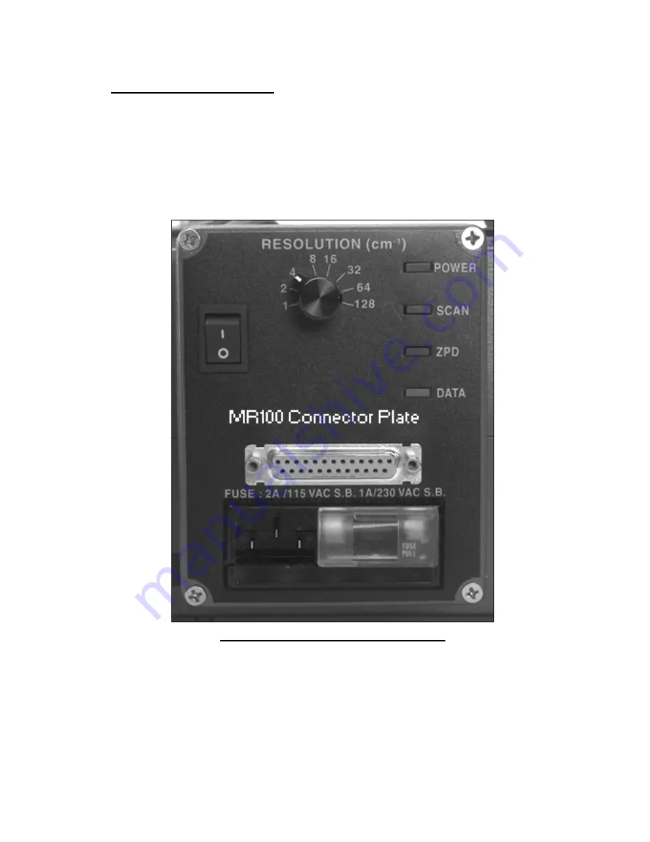
MR100 connector plate showing DB-25 connector
MR100: In addition to the data connector, the resolution setting knob, the AC power inlet, input power
selection, on-off switch and status LED’s can be found on this connector plate. The POWER led is
always on when the instrument is powered up. The other LEDs are used to provide the instrument status
during power and operation. When the instrument is first turned on the SCAN and DATA LEDs comes
on to indicate that the instrument is searching for the ZPD position. Once the ZPD is located the ZPD
LED comes on and the SCAN LED is turned off. When the instrument starts normal scanning the ZPD


