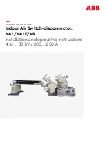
background image

DISTRIBUTION SOLUTIONS 

Indoor Air Switch-disconnector, 

NAL/NALF/VR

Installation and operating instructions
4.16 ... 38 kV / 200...1250 A

Summary of Contents for NAL Series

Page 1: ... DISTRIBUTION SOLUTIONS Indoor Air Switch disconnector NAL NALF VR Installation and operating instructions 4 16 38 kV 200 1250 A ...

Page 2: ...2 ...

Page 3: ...mmendations for receipt handling and storage of equipment 012 6 1 Switch disconnector type NAL NALF VR alternative assemblies 013 7 0 Installation 013 7 1 Before installation 013 7 2 Preparation of the switch for installation Fig 1 013 7 4 Preparation of the supporting structure 014 7 5 Installation of the switch disconnector 015 8 0 Cable connections to NAL F terminals 015 8 1 How to install the ...

Page 4: ... Mounting of fuse base 031 13 2 Mounting of the fuse tripping Fig 45 031 13 4 Fuse tripping Table of contents 032 14 0 Mounting of earthing switch type E 032 14 1 Mounting of earthing switch type E EB Fig 47 032 14 2 Mounting the earthing switch to the switch disconnector type NAL VR 033 14 3 Mounting the earthing switch to the fuse switch disconnector type NALF VR 033 14 4 Mounting the mechanical...

Page 5: ...045 17 2 Motor drive settings for A mechanism 047 17 3 Motor drive settings for K mechanism 048 17 4 UEMC 41 049 18 0 Service and maintenance 049 18 1 Cleaning 049 18 2 Switch disconnector in service 050 18 3 Mechanical overhaul 050 18 4 Electrical overhaul in service 050 18 5 Control of NAL VR knives after mounting Fig 105 106 054 19 0 Replacement of parts 12 24 kV 055 19 1 Replacement of contact...

Page 6: ...e of rapid outside temperature change to avoid condensation 2 For the normal indoor service condition water condensation max 2 times a year and low pollution level there is no need to do any special test of indoor switch disconnectors For more severe conditions the substation with applicable components needs to be classified and tested according to IEC 62271 304 3 The regular NAL F and VR with BMC...

Page 7: ...e installation in good condition throughout it s assumed lifetime Final product performance needs to be tested in final application determine the position of the main contacts which is a big advantage 9 ABB recommends to verify the position of the main knives before and after each operation ABB recommends to install air insulated switch disconnectors in applications where it is possible to visuall...

Page 8: ...resent an attractive solution as the main switching apparatus for applications in enclosed switchgear and compact transformer stations In combination with ABB CEF current limiting fuses they provide reliable control over the full range of overload currents Main areas of application NAL NALF VR switch disconnector as line and transformer switches within distribution networks as motor switches 2 0 I...

Page 9: ...s NALF VR is the ideal solution for the protection of the majority of faults in modern electrical networks It combines NAL VR which interrupts load currents up to 1250A and small fault currents with the fuse base F for breaking large short circuit currents The NAL switch disconnector family meets the following standards depends on the product variant and voltage level IEC 62271 1 EC 62271 102 IEC ...

Page 10: ... with the ISO 14001 Standard Guidelines for environmental management The production processes are carried out in compliance with the Standards for environmental protection in terms of reduction in energy consumption as well as in raw materials and production of waste materials All this is thanks to the medium voltage apparatus manufacturing facility environmental management system ...

Page 11: ...lation activities shall be performed by specialists with valid licenses only Always follow these instructions closely If you have any questions or doubts please contact the proper ABB personnel Only original parts provided by PLABB should be used _ WARNING Careless handling of high voltage can result in serious injury or death Before carrying out of any maintenance installation of apparatus read t...

Page 12: ...aratus Check the apparatus condition directly after receipt Any damages should be reported to the transporter forwarder and manufacturer Make sure that the product is complete and complies with the order Be careful during transportation of apparatus Never lift apparatus by grabbing current knives main shaft or insulators because it may cause switch damage Before installing keep switches only in or...

Page 13: ... Topas NCA 52 In case of NAL 12 17 24 36 with A mechanisms make sure that the push rods are removed from the main shaft 7 2 Preparation of the switch for installation Fig 1 For switches with A mechanisms the contact knives must be fully opened by hand and the draw bars connected to the cranks Before the switch is test operated it should be checked that the surfaces of the main contact are covered ...

Page 14: ...ing lever will hit the lock To avoid these defects coming from deformations of the supporting structure it is recommended to tighten initially three bolts only when fixing the base Some additional washers shall be placed under the fourth bolt to prevent deformations of the switch base when tightening the fourth bolt During installation be careful and do not apply high should be 40 Nm 10 torque on ...

Page 15: ...d the nut by more than 2 3 threads after tightening Fig 5 8 1 How to install the medium voltage cable lug 2 Proper cable lug connection 3 Proper cable lug connection 4 Recommended assembly method of medium voltage cable lug 5 Proper connection with the switch disconnector terminal Upper side Lower side 8 0 Cable connections to NAL F terminals Max 2 3 thread _ WARNING Improper installation of cable...

Page 16: ...ction bolt used is too long The bolt should have sufficient length See Fig 3 Cable lug installation on the incorrect side of the switch terminal Cable lug cannot be fixed from the terminal lower side Fix it as shown on Fig 3 6 Direction of the screw thread 7 Recommended method of screwing connection 8 Cable lugs properly connected to the switch disconnector terminal 9 Example of mounting with too ...

Page 17: ... accordance to the required voltage level For NAL F installation in the pre fabricated substations or CSS please refer to manufacturer manuals The pre fabricated substations or CSS manufacturer is responsible for ensuring the operating conditions in the station according to the design class of installed devices see IEC 62271 304 The regular NAL F with BMC Bulk Dough Moulding Compounds insulators i...

Page 18: ...ned after installing the bevel gears as visible on Fig 16 The angle of the operating tube must not exceed 40 see Fig 17 Drilling of the operating tube see Fig 18 9 1 Instruction of installation and adjustment of switch disconnector type NAL NALF VR with hand operation mechanism HE 9 0 Mounting the hand operating mechanism type HE _ WARNING Always apply the information label supplied with the drive...

Page 19: ...m see Fig 14 3 Install the bevel gear on the NAL NALF VR and earthing switch shaft Be sure the orientation of the gear wheels has been properly assigned the bigger wheel position is important This position is clearly shown on Fig 15 In case of earthing switch the knurled end shaft on which the bevel gear is installed must be mounted on the earthing switch shaft using the long slotted hole 13 NAL i...

Page 20: ...2 5 size with torque 3 Nm see Fig 16 5 Install the hand operating mechanism HE Put the connection rod tube 26 9 mm between cardanic joint and bevel gear Maximum angle is 40o see Fig 17 6 Mark the position of the hole for the safety pin hole and do not make a bigger hole than 10 1 mm see Fig 18 16 HE hand operating mechanism 17 Hand operating mechanism 18 Connecting rod ...

Page 21: ... 23 Put the operating handle on the splined end Turn the handle anticlockwise to charge A mechanism opening spring apply to A mechanism 24 A mechanism opening spring is charged 22 The shaft should loosely rotate loosely after taking out the arrestor ring 20 Take out the Seeger ring spring and nut ...

Page 22: ...22 MOUNTING AND OPER ATION MANUAL INDOOR AIR SWITCH DISCONNECTOR NAL NALF VR 25 Turn the handle to the left and right for test 26 Put the arrestor ring on the shaft ...

Page 23: ...n picture 22 slide out the arrestor ring from the shaft and turn 2 3 teeth to the right 31 Check the opening spring is charged After adjustment the Seeger ring spring and nut should be put back on the HE shaft 30 Correctly position the arrestor ring in closed position 28 Check if the arrestor ring and switch disconnector are in locking position ...

Page 24: ... earthing switch can take place only after confirming that the switch disconnector is in open position Fig 105 10 1 Adjustment of the hand operating mechanism type HE 10 2 K mechanism Fig 32 Closing 1 If the switch disconnector is equipped with earthing switch be sure that it is in the open position Fig 105 2 Make sure that all doors of the station are closed 3 Remove the padlock securing manual d...

Page 25: ... great speed and force Always keep a safe distance from moving parts of the switch Be careful especially with type A dou ble spring mechanism This kind of drive stores great energy and can release it by small rotation of shaft Closing 1 If the switch disconnector is equipped with earthing switch be sure that the earthing switch is in the open position Fig 105 2 If the switch disconnector is equipp...

Page 26: ...rformed by installing padlock that prevents inserting the maneuvering lever and blocking the position of the front lever Please specify the type of apparatus NAL F switch or E EB earthing switch to which the drive is required when placing order 11 2 Rated data Fitter s lock with a padlock MAX 90o manoeuvring angle of rotation Mechanical performance of 2000 operations Hand operating mechanism for N...

Page 27: ...d for mounting on the front wall of application panel 1YMX888740M0001 NEMD drive for E EB earthing switches designed for mounting on the side wall of application panel 1YMX888741M0001 NEMD drive for NAL switch disconnectors intended for installation below the switch disconnector level 1YMX888742M0001 NEMD drive for E EB earthing switches intended for installation be low the switch disconnector lev...

Page 28: ...ixed to the switch frame Usually the switch disconnector is delivered without shaft extension for left hand side operation 12 0 Replacing the mechanism on the switch 1 1 1 4 A3 Sheet No Format Language Scale Subtitle Type Derived from Name Date Location Revision Drawn Checked Approved EC No EN Drawing status Title Drawing No Responsible ABB Switzerland Ltd Weight Material Surface Surface code D C ...

Page 29: ...01 1 pcs 3 Wave washer DIN137A 2 psc 4 Nut M8 DIN934 2 psc Check if the shaft extension works properly with a few operations 12 2 Test operation of A mechanism Current knives rotate with great speed and force Always keep a safe distance from moving parts of the switch Be careful especially with type A double spring mechanism This kind of drive stores great energy and can release it by small rotati...

Page 30: ...13 7 5 6 7 12 11 1 11 9 8 1 2 3 4 MEC 10 max e 8 mm e DIN 43625 41 Switch disconnector type NALF mounted on the pivot side 43 Fuse tripping 44 Tripping rod 42 Switch disconnector type NALF mounted on the oppening side _ CAUTION 1 The switch disconnector must be open and main springs not charged 2 If contact plastic covers are added to box with apparatus component A Fig 41 these covers must be asse...

Page 31: ... 60 and return the operating handle back to the neutral position opening spring housing F see Fig 46 must not be latched 2 Mount a new fuse link or a test fuse which is in accordance with DIN 43625 in one of the phases The fuse links for switch fuse combination with fuse tripping system must come form NALF NALFWind 36 reference list of fuse links to ensure proper coordination between switch discon...

Page 32: ...ch slowly operate the earthing switch using a handle placed on knurled end shaft installed on short hole and adjust the fixed contacts to line up correctly with moving contacts Tighten the contacts screws Contact knife with draw bar should be tightened in two steps initial torque 32 Nm 10 final torque 40 Nm 10 47 Earthing switch type E mounted on the NAL VR switch disconnector 47a Tighten the eart...

Page 33: ...plate on the operating shafts of the switches Do not forget to mount the two distance rings E on the two screws F Mount the interlock connection B Mount the interlock rings C and D on the shafts with the flat part of the ring facing towards the interlock connection B see Fig 50 Do not forget to mount the two distance rings E on the two screws F 51 Earthing switch type EB12 48 The switch disconnect...

Page 34: ... pin to secure the perforated disk 5 9 After installation check the operation of the shunt trip and its cooperation with the mechanism Turn the operating mechanism shaft to a maximum angle of 60 clockwise and tighten mounting screws 2 with 25 Nm torque Mounting the shunt release Fig 52 1 Turn the operating mechanism shaft to a maximum angle of 60 clockwise 2 Opening spring housing F see Fig 46 mus...

Page 35: ...contacts conform to the following standards regulations directives EN 60947 DC 21A DC 22A DC 23A AC 21A RoHS Directive 16 0 Mounting the auxiliary switch General characteristics Insulation voltage to standard VDE 0110 Group C 660 V AC 800 V DC Rated voltage 24V 660 V Test voltage 2 kV for 1 min Maximum rated current 10 A 50 60 Hz Breaking capacity Class 1 IEC 62271 1 Number of contacts 5 Groups of...

Page 36: ... AND OPER ATION MANUAL INDOOR AIR SWITCH DISCONNECTOR NAL NALF VR 53 Auxiliary switch mounted on NAL 55 Auxiliary switch 57 Auxiliary switch position 54 Auxiliary switch mounted on NAL 56 Auxiliary switch position ...

Page 37: ...point of auxiliary switch 16 2 Mounting the auxiliary switch for E EB earthing switch Fig 60 71 Electrical signalling of earthing switch open closed can be obtained with a group of 2NO 2NC 4NO 4NC auxiliary contacts The auxiliary switch is mounted to the frame on the right side of the earthing switch and connected to the main shaft ...

Page 38: ...nnecting part with a hole is mounted on the extension shaft of earthing switch so that the rod connecting the arm of auxiliary switch with shackle is slightly strained 63 The arm of auxiliary switch should be at an angle 45 50 degrees in direction of earthing switch 66 Tighten the screws M5 that mount the shackle on extension shaft of earthing switch 67 Tighten the screws M5 that mount the shackle...

Page 39: ... for fuse interruption The open fuse auxiliary switch can only be installed on the A mechanism and a fuse base equipped with fuse tripping This switch has two contacts one normally open and one normally closed It is actuated by the fuse tripping tie rod linkage connected to the type CEF fuse base Locate the mounting hole and slot on the side of the A mechanism with the operating shaft shown in fig...

Page 40: ...ent to the white roller on the switch as shown in figure 75 Bolt the open fuse auxiliary switch to the mounting hole on the A mechanism and loosely install the screw hardware to allow the switch to rotate into the slot pictured in figure 73 Place the white disk onto the half moon shaft and rotate the switch into place as shown in figure 74 73 74 75 ...

Page 41: ...echanism Rotate the white disk until it reaches its maximum rotation and contacts the switch as in figure 77 An audible click should be heard If not remove the white disk and move the long bolt and nuts to the appropriate hole Once adjusted properly secure the switch with a 13 mm socket and Phillips screw driver Install the circlip onto the half moon shaft to secure the white disk as shown in figu...

Page 42: ...ing bracket with a Phillips screw driver as seen in figure 79 Slide the switch onto the studs located on the motor bracket and secure with the provided nuts Place the white plastic disc onto the half moon shaft as shown in figure 80 Rotate the white plastic disc to its maximum rotation and mark the hole adjacent to the white roller on the open fuse auxiliary switch as shown in figure 81 79 80 81 ...

Page 43: ...s maximum displacement and listen for a click This indicates that the switch will make contact If a click is not heard relocate the screw to a closer hole Ensure the white disc reaches its maximum rotation just as the click is heard to prevent over rotation If the setup is correct secure the white disc with the provided cir clip onto the half moon shaft 82 83 ...

Page 44: ...e NAL NALF VR mechanism shaft where UEMC 41 can have more possibilities to be connected to switch disconnector _ CAUTION The pushbuttons on the box must not be held for more than 5 6 seconds The button only initiates the closing or opening process It has its own support and there is no need to keep pressed _ CAUTION In case of any installation maintenance of switchdisconnector NAL VR equipped with...

Page 45: ...MU motor drive on A mechanism 87 HE lower part for motor operation a and manual operation b There is also possibility to add blocking coil b 2 NAL NALF VR must be in open position and discharge both springs Locate the spacer bracket mounting holes on the A mechanism see Fig 88 89 Tighten mounting screws with 25 Nm torque 1 Check that the motor drive is working correctly 3 To reduce side shake turn...

Page 46: ...CTOR NAL NALF VR 92 Before mounting on the A mechanism shaft set up distance to 4 8 mm 93 Mounting of standard motor drive for NAL NALF VR on A mechanism 94 Mount the standard motor drive for NAL NALF VR on the shaft and tighten mounting screws with 25 Nm torque ...

Page 47: ...e 3 5 mm 100 Mounting of standard motor drive for NAL NALF VR on Kmechanism 96 NAL 12 in open position NAL NALF VR must be in open position Locate the spacer bracket mounting holes on the K mechanism Fully tighten mounting screws See Fig 95 96 17 3 Motor drive settings for K mechanism Mount the standard motor drive for NAL NALF VR F on the shaft and tighten mounting screws with 25 Nm torque See Fi...

Page 48: ...s of UEMC 41 drives 1 UEMC 41 drive 2 Manual operating handle 1YMX053235M0004 3 Connecting rod 1YMX000004 4 Bevel gear 1YMX053362M0002 5 Bevel gear base YMX343036M0001 6 Rod connector 1YMX000053M0001 Length depends on client needs For detailed instruction of installation and maintenance please refer UEMC 41 manual 102 UEMC 41 drive with external control box _ 104 Typical UEMC 41 installation with ...

Page 49: ...d maintenance must be performed in a professional way to keep the installation in good condition throughout it s lifetime When special operating conditions occur the service intervals and service scope should be adjusted individually preventing the switch to be stressed over its performance limits The switch disconnectors with design class suitable for special operating conditions like NAL H shoul...

Page 50: ...ould be carried out after max 1000 operations or 15 years in service preferably by ABB s staff 18 4 Electrical overhaul in service The frequency of overhaul depends also on the number of operations and the magnitude of the breaking current After 100 operations at rated current the main contacts the arcing contacts and the arc extinguishing chamber should be inspected and replaced if one of below c...

Page 51: ... Management PL PSY M Mańkowski PLABB Opening side Closed position Open position Open position Closed position Earthing switch Switch disconnector 105 Open and close position of switch disconnector with earthing switch 18 5 Control of NAL VR knives after mounting Fig 105 108 Due to possible differences in the flatness of the wall and support frame it is necessary to check the position of the main k...

Page 52: ... be used if additional grease is required 4 Operate the switch several times 5 Check the main contact position at closed switch disconnector 6 After all adjustments this position must be in accordance with adjusting specification shown on Fig 106 in case of fixed contact with a height of approximately 38 mm main contact in closed position should be between two extreme positions 2 mm above and 4 mm...

Page 53: ...ived from Name Date Location Revision Drawn Checked Approved EC No EN Drawing status Title Drawing No Responsible ABB Switzerland Ltd Weight Material f m c v H L K PROPRIETARY AND SECRET INFORMATION The information contained in this document has to be kept strictly confidential Any unauthorized use reproduction distribution or disclosure to third parties is strictly forbidden ABB reserves all righ...

Page 54: ...n blow out the small particles in the threaded hole use eye protection When mounting the screws must be inserted carefully into the threads in the insulator and tightened with care correct torque see Fig 114 If using a new insulator the holes should be threaded to about 10 m deep by the self tapping screw before mounting Remove the screw and blow the holes clean The mounting takes place according ...

Page 55: ... firmly at the pivot point but without jerking 5 Attach the draw bar to the main shaft by the eccentric bolt 2 3 and secure with washer and circlips 2 1 6 The depth of the engagement between the fixed and the moving contact can be adjusted by the eccentric bolt 2 3 or by moving the insulator 2 REPL ACEMENT OF PARTS 12 24 K V 111 Support insulator with knife complete _ WARNING These operations shal...

Page 56: ...lators put silicone rubber bumper 3 11 between main contact and insulator as it is indicated in the drawing 4 Damaged parts must be replaced take care that the arcing contacts 3 6 are correctly placed in the pressure spring 3 7 by mounting the thermal disc 3 4 and the arcing chamber 3 3 the main contact 3 5 must be pressed firmly against the hollow insulator 3 8 Attach the whole assembly by the sc...

Page 57: ...rawing status Title Drawing No Responsible 1YMX000271M0136 ABB Switzerland Ltd Weight Material f m c v H L K X X PROPRIETARY AND SECRET INFORMATION The information contained in this document has to be kept strictly confidential Any unauthorized use reproduction distribution or disclosure to third parties is strictly forbidden ABB reserves all rights regarding Intellectual Property Rights Thread Qu...

Page 58: ... 5 Check that the contact knives can move easily and operate correctly over the opposite contacts 6 Before the drawbar is connected to the crank arm of the operating shaft see Fig 116 ensure that the auxiliary knives run easily in the individual arc extinguishing chambers and that the main knives make proper contact 7 Put contact grease on the main contacts before the first test operation The cont...

Page 59: ...or Fig 119 1 Disconnect the switch disconnector 2 Contact block with contact knives is dismounted use spanner gap 17 3 The insulators are attached to the switch frame by a screw M12 spanner gap 19 The insulator is dismounted and a new insulator is mounted to the switch frame 4 Contact block with contact knives is mounted to the insulator and adjusted as described in paragraph Hollow insulator with...

Page 60: ...rque for screws NAL VR 36 40 5 _ WARNING These operations shall be carried out by authorised ABB service only _ Note Piston and cylinder MUST NOT be greased or lubricated _ Note A certain degree of adjustment can be made by moving the hollow insulator 21 4 Replacement of the hollow insulator Fig 120 1 Disconnect the switch disconnector 2 The spring mechanism is removed from the frame 3 All draw ba...

Page 61: ...wn in the picture below 126 Insert pin 3 in the shaft hole 127 Put on washer 2 and safety ring 1 22 0 Adjustment of splined shaft end for earthing switch Fig 123 127 _ CAUTION In case of changing the operating side of earthing switch and mechanical interlocking splined shaft end location should be updated accordingly 1 2 3 3 1 2 ...

Page 62: ...titute equipment facilities or services downtime costs delays and claims of customers of purchaser or costs connected with interruption of operation loss of anticipated savings or for any special indirect or consequential damage or loss of any nature whatsoever This limitation of liability provisions mentioned above shall prevail over any conflicting or inconsistent provisions contained in any of ...

Page 63: ...12 50 4 2 90 3 48 CEF 6 12 10 292 442 1YMB711216M2512 1YMB711216M4512 NALF 12 kV 75 4 4 30 5 16 CEF 6 12 10 292 442 1YMB711216M2512 1YMB711216M4512 100 4 5 80 6 96 CEF 6 12 16 292 442 1YMB711218M2512 1YMB711218M4512 125 4 7 20 8 64 CEF 6 12 16 292 442 1YMB711218M2512 1YMB711218M4512 160 4 9 20 11 04 CEF 6 12 20 292 442 1YMB711219M2512 1YMB711219M4512 200 4 11 50 13 80 CEF 6 12 20 292 442 1YMB71121...

Page 64: ...7 5 20 292 367 442 1YMB711719M2512 1YMB711719M3512 1YMB711719M4512 315 4 12 10 14 52 CEF 10 17 5 20 292 367 442 1YMB711719M2512 1YMB711719M3512 1YMB711719M4512 400 4 15 40 18 48 CEF 10 17 5 25 292 367 442 1YMB711721M2512 1YMB711721M3512 1YMB711721M4512 500 4 19 20 23 04 CEF 10 17 5 31 5 292 367 442 1YMB711724M2612 1YMB711724M3512 1YMB711724M4512 630 4 24 20 29 04 CEF 10 17 5 40 292 367 442 1YMB711...

Page 65: ...512 800 5 23 10 27 72 CEF 10 24 31 5 442 537 1YMB712424M5512 1YMB712424M5512 1000 5 28 90 34 68 CEF 10 24 40 442 537 1YMB712425M5512 1YMB712425M5512 1250 5 36 10 43 32 CEF 10 24 50 442 537 1YMB712427M5612 1YMB712427M5612 1600 6 46 20 55 44 CEF 10 24 63 442 537 1YMB712429M5612 1YMB712429M5612 2000 6 57 70 69 24 CEF 10 24 80 442 537 1YMB712431M5612 1YMB712431M5612 30 36 751 4 1 40 1 68 CEF 20 36 6 3...

Page 66: ...1M4611 400 4 11 5 13 9 CEF S 10 24 40 442 1YMB742425M4611 500 4 14 4 17 3 CEF S 10 24 40 442 1YMB742425M4611 630 4 18 2 21 8 CEF S 10 24 50 442 1YMB742425M4611 800 5 23 1 27 7 CEF S 10 24 50 442 1YMB742425M4611 10002 5 24 1 28 9 CEF S 10 24 50 442 1YMB742425M4611 30 36 754 4 1 4 1 7 CEF S 30 40 5 6 3 537 1YMB744014M5611 NALF Wind 36 kV 1004 4 1 9 2 3 CEF S 30 40 5 6 3 537 1YMB744014M5611 125 4 2 4...

Page 67: ...16M4512 NALF 12 kV 100 4 5 2 6 3 CEF S 6 12 16 292 1YMB741218M2611 200 4 10 5 12 6 CEF S 6 12 20 292 1YMB741219M2611 315 4 16 5 19 8 CEF S 6 12 25 292 1YMB741221M2611 500 4 26 2 31 5 CEF S 6 12 40 292 1YMB741225M2611 630 4 33 1 39 7 CEF S 6 12 50 292 1YMB741227M2611 800 5 42 0 50 4 CEF S 6 12 63 292 1YMB741229M2611 1250 5 65 6 78 7 CEF S 6 12 63 292 1YMB741229M2611 22 24 50 4 1 3 1 6 CEF 10 24 6 3...

Page 68: ...x 6 kg Yes Re use or use as energy additive in refuse incineration Wooden pallet 7 5 kg Yes Re use or use as energy additive in refuse incineration Epoxy 33 No Store in appropriate places indented for this purpose 25 1 Environmental Certification Life expectancy of product The product is developed in compliance with the requirements denoted by IEC 62271 200 The design incorporates a life span unde...

Page 69: ...amine Ethylene glycol Fluorodichloromethane Formic acid concentrated Furfuralcohol Gasoline 5 methanol Glacial acetic acid Hydrazine hydrate 80 Hydrochloric acid concentrated Isoamyl alcohol Isopropanol Methylene chloride Methyl ethyl ketone Nitric acid 2 Nitric acid 10 Nitric acid 30 Potassium chlorate N propanol Propylene glycol Sulfuric acid concentrated Sodium hydroxide solution 5 10 50 Tartar...

Page 70: ...shall prevail ABB AG does not accept any responsibility whatso ever for potential errors or possible lack of information in this document We reserve all rights in this document and in the subject matter and illustra tions contained therein Any reproduc tion disclosure to third parties or utilization of its contents in whole or in parts is forbidden without prior written consent of ABB AG ...

Page 71: ...71 ...

Page 72: ...cifications subject to change without notice For more information please contact ABB Contact Center tel 48 22 22 37 777 e mail contact center pl abb com ABB Sp z o o Branch in Przasnysz 59 Leszno Str 06 300 Przasnysz Poland Phone 48 22 22 38 900 Fax 48 22 22 38 953 www abb pl ...

Reviews: