


17
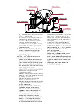
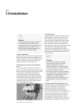
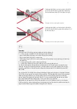
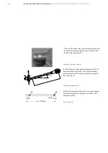
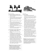
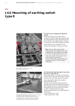
Cable lug installation on the incorrect side of the
switch terminal. Cable lug cannot be fixed from
the terminal lower side. Fix it as shown on Fig.3.
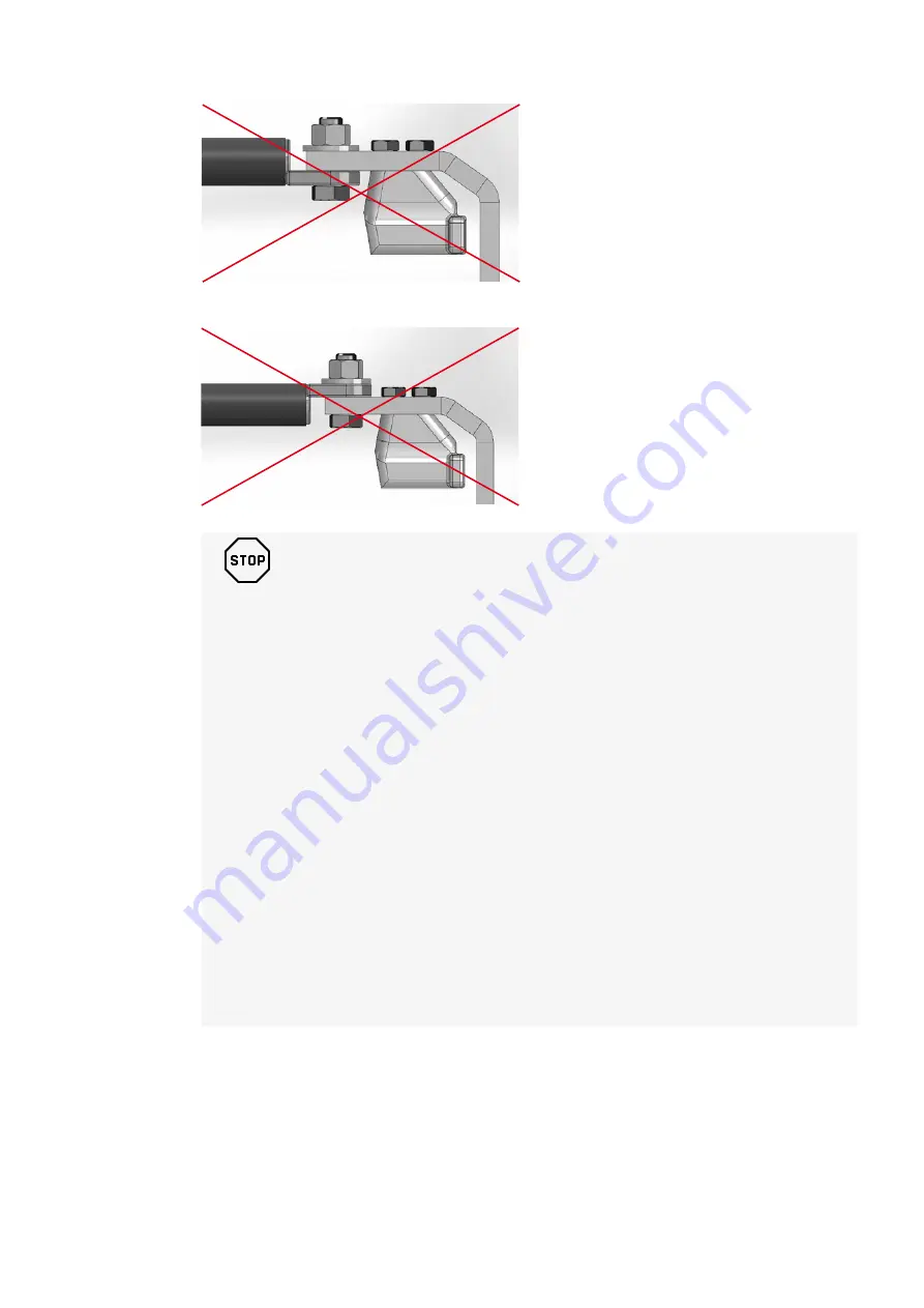
Cable lug installation on the incorrect side of the
switch terminal. Cable lug cannot face down. Fix it
as shown on Fig.3.
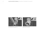
—
11 Example of incorrect cable lug side installation
—
12 Example of incorrect cable lug side installation
_
WARNING!
Ignoring these instructions can cause damage to the equipment:
1. Ensure proper installation of the cable lugs on the terminals
• Do not install cable terminal on the side of the earthing switch
• Do not install cable terminal in reverse way.
• Utilize proper length of bolts in such a way that bolt thread does not excessively protrude from
the cable lug.
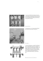
2. Ensure good quality work on cable terminations.
3. Ensure that clearances are in accordance to the required voltage level.
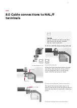
For NAL/F installation in the pre-fabricated substations or CSS please refer to manufacturer
manuals. The pre-fabricated substations or CSS manufacturer is responsible for ensuring the
operating conditions in the station according to the design class of installed devices (see IEC
62271-304).
The regular NAL/F with BMC (Bulk (Dough) Moulding Compounds) insulators is designed to class
0 (C
0
P
L
) that corresponds to normal service conditions. The standard NAL works fine everywhere
these operating conditions are provided. Wherever we observe harsh operating conditions,
special type of the switch-disconnector NAL/F-H is recommended that has been type tested
according to IEC 62271-304 design class 2 for severe operating conditions.
Regardless of the type of the switch-disconnector in use, all installation work, station design,
location selection, ground preparation, and maintenance must be done in a professional way to
keep the installation in good condition throughout it's lifetime.


