


5 Flowmeter upgrade procedure
Navigator 550 | Hydrazine and sodium wet-sections | Flowmeter upgrade procedures (single-stream and multi-stream) |
INF13/141–EN Rev. B
3
5 Flowmeter upgrade procedure
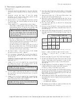
Referring to Fig. 4.1:
1. Disconnect external sample tubing
A
from each inlet hose
connector
B
on underside of the wet-section and allow to
drain.
2. Disconnect sample inlet tubes
C
from the barbed
connectors
D
on the top of each inlet assembly
E
and
discard stream 2 and stream 3 tubing.
3. Loosen locknuts
F
on the underside of each inlet assembly
E
and pull each inlet assembly adaptor out from the top side
of the wet-section.
4. Fit new adaptors
G
(1 supplied with each kit) as follows:
–
fit the stream 1 adaptor (single- and multi-stream) into the
inlet hole below locknut
H
and secure in position using
locknut
H
on the top face of the wet-section base.
–
for stream 2 (sodium multi-stream only), punch- or cut-out
the knock-out below locknut
I
, fit the stream 2 adaptor
into the inlet hole and secure in position using locknut
I
on the top face of the wet-section base.
–
for stream 3 (sodium multi-stream only), punch- or cut-out
the knock-out below locknut
J
, fit the stream 3 adaptor
into the inlet hole and secure in position using locknut
J
on the top face of the wet-section base.
5. Re-connect stream 1 sample inlet tube
C
to the barbed
connector on the new stream 1 adaptor.
6. Push the stream 1 flowmeter
K
into the QD coupling
L
ensuring the flow arrow on the flowmeter body is facing into
the wet-section.
Hydrazine and sodium single-stream wet-sections only
–
proceed to step 11.
7. Connect a 190 mm (7.5 in.) length of new sample inlet tube
M
between the stream 2 (S2) manifold inlet
N
and the
barbed connector on the stream 2 adaptor.
8. Push the stream 2 flowmeter into the stream 2 QD coupling
ensuring the flow arrow on the flowmeter body is facing into
the wet-section.
9. Connect a 245 mm (9.6 in.) length of new sample inlet tube
O
between the stream 3 (S3) manifold inlet
P
and the
barbed connector on the stream 3 adaptor.
10. Push the stream 3 flowmeter into the stream 3 QD coupling
ensuring the flow arrow on the flowmeter body is facing into
the wet-section.
11. Remove and retain the 4 PCB cover fixing screws and
washers
Q
and remove PCB cover
R
.
12. Remove the upper cable gland blanking plug from the top
right-hand side of the PCB housing taking care not to lose the
locking nut on the inside.
13. Fit a new cable gland
S
in place of the blanking plug
removed at step 12.
14. Punch- or cut-out the hole
T
in the base of the wet-section
and feed each flowmeter cable (supplied) through and up to
the PCB housing.
15. Feed the each cable through cable gland
S
and connect the
flowmeter wires to the PCB terminal block numbers shown in
Table 4.1:
*Stream 1 – sodium and hydrazine single-stream wet-sections
**Streams 2 / 3 used with stream 1 for sodium multi-stream
wet-sections
16. Tighten cable gland
S
to seal the cable(s) into the gland.
17. Connect each cable to the correct flowmeter cable connector
(stream 1 cable connector to flowmeter S1, stream 2 cable
connector to flowmeter S2, stream 3 cable connector to
flowmeter S3).
18. Change the (external) sample lines or adapt to
3
/
8
in. ID flexible
tubing and fit onto the correct inlet of each flowmeter.
If necessary, secure using a hose clip or similar.
19. Ensure the O-ring
U
between the PCB housing and cover is
located correctly in the PCB housing groove and refit the PCB
terminal cover
R
to the PCB housing using the 4 PCB cover
fixing screws and washers
Q
.
20. Restore power to the transmitter and refer to the wet-section
Operating instructions to configure the software to enable the
flowmeter(s):
–
OI/ASO550-EN Sodium
–
OI/AHM550-EN Hydrazine
21. Re-introduce sample to the wet-section and check that the
flowrate is displayed on the transmitter.
Note.
If upgrading a single-stream wet-section, fit
the new stream adaptor in the 2
nd
inlet hole from the
right in the base. The hole must be punched or cut
out of the knock-out.
Caution.
Inlet tubing must be the specified length and
type to ensure correct operation.
Caution.
Inlet tubing must be the specified length and
type to ensure correct operation.
Terminal number / cable color
Multi-stream
Single-stream
Stream 1*
13
Red
15
Brown
17
Black
13
Red
15
Brown
17
Black
Stream 2**
19
Orange
21
Yellow
23
Green
Stream 3**
20
Blue
22
Violet
24
Grey
Table 5.1 Streams 1, 2 and 3 – terminal connections / wire colors


