background image

— 

A B B ME A SUR EMENT & A N A LY TIC S  |  INSTRUC TION  |  INS/A N A INST/0 2 5 - EN R E V. B
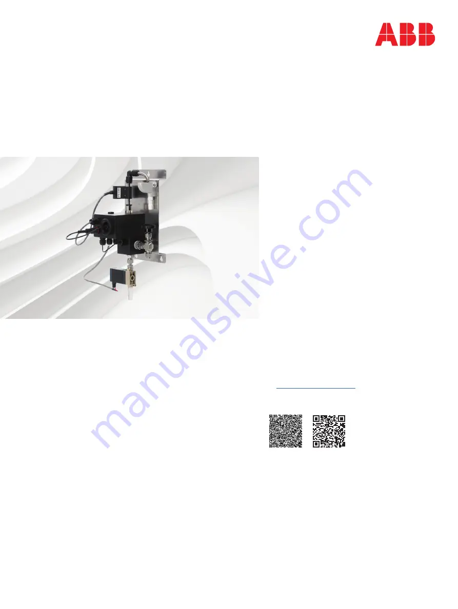
Navigator ADS551

Low level dissolved oxygen

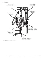
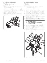
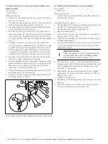
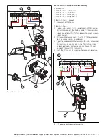
Replacement / Upgrade procedures 
– wet section spares,
kit references: 
• flowcell 
• tundish
• flowmeter 
• drain valve 
• Modbus cable

Measurement made easy
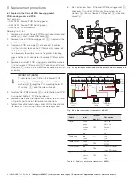
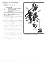
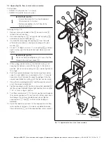
1  Introduction

This publication details replacement / upgrade 
procedures for the following Navigator ADS551 wet 
section spares:

Before carrying out any procedures, read Section 3 – 
Health & Safety. These procedures must be carried 
out by a suitably-trained technician.

Tools required

•  Pozidrive screwdriver
•  Slot-head terminal screwdriver
•  Anti-static strap
•  Spanners (adjustable)

2  For more information

Further information is available from: 
 

www.abb.com/analytical

or by scanning these codes: 
 

Sales Service

Navigator ADS551 
wet section

Summary of Contents for Navigator ADS551

Page 1: ...tails replacement upgrade procedures for the following Navigator ADS551 wet section spares Before carrying out any procedures read Section 3 Health Safety These procedures must be carried out by a suitably trained technician Tools required Pozidrive screwdriver Slot head terminal screwdriver Anti static strap Spanners adjustable 2 For more information Further information is available from www abb ...

Page 2: ...y a trained technician Chemical Ensure personal protective equipment PPE such as gloves and eye protection are worn during any maintenance Observe all health and safety procedures for handling chemicals To familiarize yourself with handling precautions dangers and emergency procedures always review the Material Safety Data Sheets prior to handling containers reservoirs and delivery systems that co...

Page 3: ...eplacement Flowcell PCB assembly Section 6 1 page 4 replacement Drain valve assembly Section 6 4 page 6 replacement Section 7 2 page 10 upgrade Modbus cable assembly Section 6 6 page 7 replacement Flowmeter assembly Section 6 3 page 5 replacement Section 7 1 page 9 upgrade Flow control valve assembly Section 6 7 page 8 replacement Section 7 3 page 11 upgrade Temperature sensor assembly Section 6 5...

Page 4: ...ixing screws 6 Remake cable connections disconnected at step 3 refer to Fig 6 2 and Table 6 1 for terminal connections 7 Tighten the cable glands plugs and LLDO connector into the flowcell PCB housing to ensure a watertight seal 8 Refit or for new items fit flowcell PCB housing gasket C and cover B using 4 PCB cover fixing screws and washers A Ensure flowcell PCB gasket C is located correctly IMPO...

Page 5: ...ailed in step 1 of Section 6 1 page 4 3 Loosen cable gland B at the flowcell PCB housing C 4 Disconnect flowmeter cable D from wet section PCB terminals TB2 see Fig 6 7 page 7 and remove cable 5 Depress the QD coupling collar E on QD coupling F and lift the top QD coupling F complete with sample outlet tube G away from the flowmeter H 6 Depress the QD coupling collar K on QD coupling L and lift th...

Page 6: ... EN 8 Connect the drain valve clip on cable connector C to the end of the drain valve coil housing 9 Reconnect the drain tube to barbed outlet connector E on bottom of drain valve B 6 5 Replacing the temperature sensor assembly Part number AW502 220 Referring to Fig 6 5 1 Depress manual override button A on drain valve B to drain the wet section Referring to Fig 6 6 page 7 2 Remove and retain 4 fl...

Page 7: ...marked white green screen black and red 3 Withdraw Modbus cable C from the PCB housing and flowcell case assembly and discard 4 Feed the replacement Modbus cable through cable gland A and remake connections to the TB1 white green screen red and black terminal connections at the wet section PCB and at the transmitter 5 Refit the PCB cover by reversing the removal procedure Fig 6 6 Replacing the tem...

Page 8: ...w control valve F and lightly nip up coupling nut C do not tighten at this stage 6 Check that sample feed pipe D and flow control valve F are in the correct orientation 7 Tighten coupling nut E on the valve outlet side and coupling nut C on the sample inlet pipe finger tight then turn another 1 to 11 4 turns using a spanner 8 Turn the flow control valve F to the shut position reintroduce the sampl...

Page 9: ...on 6 1 page 4 6 Remove blanking plug I from front of flowcell PCB housing J and replace with supplied cable gland and O ring K 7 Pass flowmeter cable L through cable gland K at flowcell PCB housing J and make connections to PCB terminal block TB2 refer to Fig 6 7 page 7 8 Tighten cable gland K to form a watertight seal 9 Check sample outlet tube G is located correctly over tundish assembly H and r...

Page 10: ...ed 6 Fit the supplied length of drain tube I onto the barbed connector J on drain valve G and route as short and straight as possible to a suitable drain 7 Remove blanking plug K from the underside of flowcell PCB housing L and replace with supplied cable gland and O ring M 8 Feed cable N from drain solenoid valve assembly G through the cable gland M and make connections to PCB terminal block TB3 ...

Page 11: ...y nip up coupling nut L it may be necessary to cut or bend the pipe to arrange it into the correct orientation for mating with the flow control valve 7 Check that sample feed pipe E and flow control valve I are in the correct orientation 8 Tighten coupling nuts K on the valve outlet side and L on the sample inlet pipe finger tight and then turn another 1 to 11 4 turns using a spanner 9 Turn flow c...

Page 12: ...hts in this document and in the subject matter and illustrations contained therein Any reproduction disclosure to third parties or utilization of its contents in whole or in parts is forbidden without prior written consent of ABB ABB 2018 3KXA494540R2001 ABB Limited Measurement Analytics Howard Road St Neots Cambridgeshire PE19 8EU UK Tel 44 0 0870 600 6122 Fax 44 0 1480 213 339 Email instrumentat...

Reviews: