


Navigator ADS551 | Low level dissolved oxygen | Replacement / Upgrade procedures – wet section spares |
INS/ANAINST/025-EN Rev. B
11
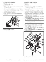
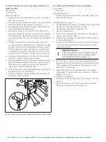
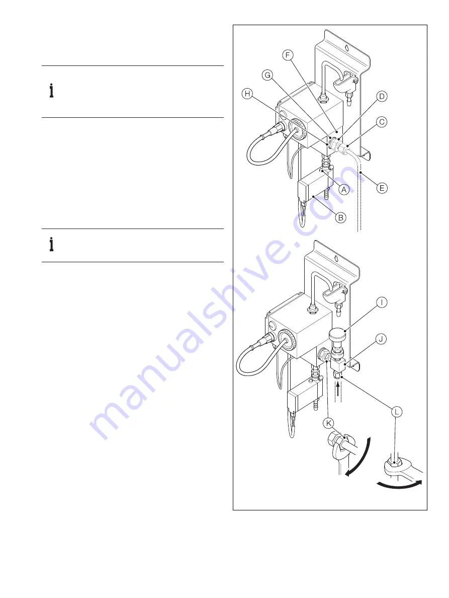
7.3 Upgrading the flow control valve assembly
Part number:
— AW502 270 (imperial, for
1
/
4
in. pipe)
— AW502 275 (metric, for 6 mm pipe)
Referring to Fig. 7.3:
1.
Depress manual override button
A
on drain valve
B
to drain the wet-section.
2.
Unscrew coupling nut
C
on sample inlet coupling
D
and remove sample feed pipe
E
.
3.
Unscrew the remainder of coupling
D
from the side
of flowcell assembly
F
and remove along with nylon
washer
G
.
4.
Fit new
3
/
8
in. BSP x 6 mm or
1
/
4
in. coupling (
D
) and new
nylon washer
G
into flowcell inlet port block
H
and
tighten.
5.
Offer up flow control valve
I
to the inlet stub
J
of
coupling
D
(above), and with the valve in the vertical
position, lightly nip up coupling nut
K
– do not tighten at
this stage.
6.
Push the sample feed pipe into the base of flow control
valve
I
and lightly nip up coupling nut
L
– it may be
necessary to cut or bend the pipe to arrange it into the
correct orientation for mating with the flow control valve.
7.
Check that sample feed pipe
E
and flow control valve
I
are in the correct orientation.
8.
Tighten coupling nuts
K
(on the valve outlet side) and
L
(on the sample inlet pipe) finger-tight and then turn another
1 to 1
1
/
4
turns using a spanner.
9.
Turn flow control valve
I
to the shut position; reintroduce
the sample upstream at a low flow rate initially and check
for leakage. If any leaks are detected, slowly tighten
coupling nuts
L
and
K
until no further leakage is
detected.
10. Open the feed line upstream to the required volume flow
rate and check for leaks. If no leaks are detected, open
flow control valve
I
until the required flow rate is present.
IMPORTANT (NOTE)
– Ensure the correct kit has been ordered
(6 mm pipe or ¼ in. pipe).
– Before proceeding, shut off flow to the
flowcell assembly.
IMPORTANT (NOTE)
Take care not to overtighten as this may strip the
thread in the inlet port block
H
.
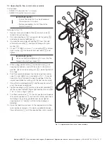
Fig. 7.3 Upgrading the flow control valve assembly
1 to 1
1
/
4
turns
1 to 1
1
/
4
turns


