


2
INS/ANAINST/025-EN Rev. B
| Navigator ADS551 | Low level dissolved oxygen | Replacement / Upgrade procedures – wet section spares
3 Health & Safety
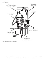
4 Overview
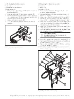
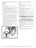
Flowcell PCB assembly, PCB housing cover, PCB housing gasket
(replacement – page 4):
— AW502 228 flowcell PCB housing gasket
— AW502 227 flowcell PCB housing cover
— AW502 225 PCB assembly
Tundish assembly
(
replacement – page 5)
:
— AW502 065 tundish assembly
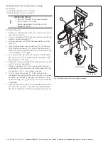
Flowmeter assembly (replacement – page 5 / upgrade – page 9)
:
— AW502 250 flowmeter assembly (upgrade kit)
— AW502 060 flowmeter assembly (replacement kit)
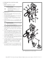
Drain valve assembly (replacement – page 6 / upgrade – page 10)
:
— AW502 240 drain valve assembly (upgrade kit)
— AW502 056 drain valve assembly (replacement kit)
Temperature sensor assembly
(
replacement – page 6)
:
— AW502 220 temperature sensor assembly
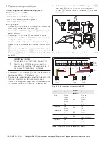
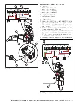
Modbus cable assembly (replacement – page 7)
:
— AW502 090 1.5 m (4.9 ft. cable)
— AW502 091 5 m (16.4 ft. cable)
— AW502 092 10 m (32.8 ft. cable)
Flow control valve (replacement – page 8 / upgrade – page 11)
:
— AW502 270 flow control valve assembly
(upgrade kit – imperial)
— AW502 275 flow control valve assembly
(upgrade kit – metric)
— AW502 068 flow control valve assembly
(replacement kit – imperial)
— AW502 069 flow control valve assembly
(replacement kit – metric)
WARNING – Bodily injury
These procedures must be carried out by a trained
technician.
Chemical
– Ensure personal protective equipment (PPE) such
as gloves and eye protection are worn during any
maintenance.
– Observe all health and safety procedures for
handling chemicals.
– To familiarize yourself with handling precautions,
dangers and emergency procedures, always review
the Material Safety Data Sheets prior to handling
containers, reservoirs and delivery systems that
contain chemical reagents and standards.
– Take care if cleaning any spillages and observe all
relevant safety instructions. Wipe up any spillages
using clean water.
Electrical
– Isolate all high voltage supplies to the transmitter
before performing replacement procedures.
– The wet-section is vulnerable to electrostatic
damage. Wear an anti-static strap or dismantle the
wet-section on an anti-static workbench.
– Ensure all electrical connections are kept dry at all
times.
General
– Shut off the external sample supply to the
wet-section and drain the flowcell - refer to the
wet-section Operating instructions (OI/ADS550-EN)
for flowcell drainage options.
– When a procedure is complete, restore power to
the transmitter and sample to the wet-section at the
correct flow rate. If necessary, calibrate the
wet-section – refer to the wet-section Operating
Instructions (OI/ADS550-EN) for calibration
instructions.
– Perform general cleaning of the wet section using a
damp cloth only – mild detergent can be used as a
cleaning aid. Do not use Acetone or any organic
solvents.


