background image


Page 2


© Copyright 2021 ABB. All rights reserved. 


Table Of Contents


Table of Contents

 ....................................................................................................................................... 

2


Foreword

 ..................................................................................................................................................... 

3


Product Information

 ................................................................................................................................... 


WARNINGS 

 .................................................................................................................................................. 

4


CAUTIONS

 ................................................................................................................................................... 

5


1:


Installer Information 

 ............................................................................................................................ 

6


1.1  General 

 ............................................................................................................................................ 

6


1.2  Equipment Included in Shipment

 .................................................................................................. 

6


1.3  Tools and Test Equipment Required for Installation and Acceptance Test  

 .............................. 

6


2:


Mechanical Installation 

 ........................................................................................................................ 

7


2.1  General 

 ........................................................................................................................................... 

7


2.2  Installation 

 ..................................................................................................................................... 

7


3:


Electrical Connections

 .......................................................................................................................... 

9


3.1  General 

 ........................................................................................................................................... 

9


3.2 120 VAC to AC Distribution Shelf FROM EACH INVERTER SHELF

................................................. 


3.3  Load Connections

 .......................................................................................................................... 

12


3.4  Load Connections (With Outlets) 

 ............................................................................................... 

13


3.5  Frame Ground Connection 

 .......................................................................................................... 

14


4:  Initial Turn On and Acceptance Procedures 

 ...................................................................................... 

15


4.1  General 

 ......................................................................................................................................... 

15


5:  AC Distribution Panel Ratings 

 ............................................................................................................ 

15


Description


Part Number


T

-

Drawing for AC Distribution Shelf


4390670T


PRODUCT MANUAL


PEC 827E 


120 VAC AC Distribution Shelf 


Summary of Contents for PEC 827E

Page 1: ...VAC AC Distribution Shelf 6180498P 23 For Conduit 6180529P 23 W Outlets 6180542P 19 For Conduit 6180533P 19 W Outlets This document issue 4ge is updated with ABB brand and contact information only no other content change from issue 4 Issue 4 release date August 2007 Jl ll ll ...

Page 2: ...t 6 2 Mechanical Installation 7 2 1 General 7 2 2 Installation 7 3 Electrical Connections 9 3 1 General 9 3 2 120 VAC to AC Distribution Shelf FROM EACH INVERTER SHELF 9 3 3 Load Connections 12 3 4 Load Connections With Outlets 13 3 5 Frame Ground Connection 14 4 Initial Turn On and Acceptance Procedures 15 4 1 General 15 5 AC Distribution Panel Ratings 15 Description Part Number T Drawing for AC ...

Page 3: ...972 244 WATT 9288 or toll free at 877 546 3243 to request a quote RETURN REPAIR For repair and return please contact 1 972 244 WATT 9288 or toll free at 877 546 3243 to request a Return Material Authorization RMA for defective equipment Product Information Please take a moment when the product is new to fill in this information This data will allow faster service when calling ABB to order accessor...

Page 4: ...f fire or may possibly cause electrical shock injury or death to personnel 5 Do not operate this equipment if it has been dropped or otherwise damaged Trying to operate this equipment if it has been damaged subjects yourself or others to electrical shock that may cause serious injury or death 6 Before you proceed ensure the input source is not live and the input circuit breaker s fuse s has been t...

Page 5: ...nt 3 To remove the circuit breakers or fuses the DC and or AC input to the plant will need to be disconnected thereby disabling the plant output to the load s Take the necessary precautions and inform the plant engineer that the plant output power to the loads will be disabled 4 Before performing any maintenance ensure AC or DC power is not applied to the plant 5 Fuse holders fuses and circuit bre...

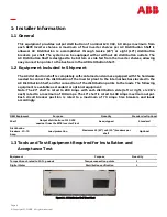
Page 6: ...ant to the internal bus bars located in the AC Distribution Shelf and for connection of the distribution points to the loads The following equipment is available as standard or optional equipment Note The 23 shelf is rated to 200 Amps with each distribution side left or right six CB s each rated to a maximum of 100 Amps The 19 shelf is rated to 100 Amps maximum output Each circuit breaker position...

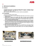
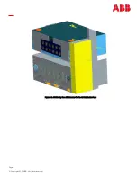
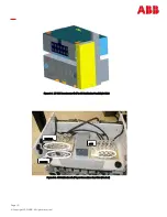
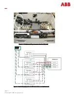
Page 7: ...disconnected This will eliminate the AC output of the Inverter shelf to help avoid potential injury C It is recommended that the AC Distribution Shelf be positioned above the inverter shelf s Secure the AC Distribution Shelf to the frame with four mounting screws locating a mounting screw at each corner of the AC Distribution Shelf Route the cable that exits the access port on the Inverter Shelf t...

Page 8: ...Page 8 Copyright 2021 ABB All rights reserved Figure 2 3 AC Wire Way from 827E Inverter Shelf to AC Distribution Panel Jl ll ll ...

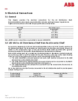
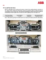
Page 9: ... block cable provided with system Connect the cables to the Inverter Shelf distribution terminal block as follows Note All AC wiring must be in conduit per the National Electric Standards Conduit knockouts are on the rear 1 2 or 3 4 for loads of the unit There is a wire way on the right looking from the rear for wiring from the inverter shelf to the AC distribution panel 1 The cable identified as ...

Page 10: ...opyright 2021 ABB All rights reserved Figure 3 1 120 VAC From Inverter Shelf to AC Distribution Panel Right Side NEUTRAL GROUND LINE Figure 3 2 AC Distribution Shelf Input Connections Rear View Unwired Jl ll ll ...

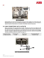
Page 11: ...gram from the 827E Inverter shelves to the distribution shelf I 1 INVERTER SHELF 11 LINE S NEUTRAL L_ 111L Wlillj J II I II I DISTRIBUTION II L II Il I I L 1 I 1 INVERTER sHELF rr 4 _ J ____c r c N F I I IISF I I J t 1 NFIITRAI I r tt Ti L b 1 N EUT RA L I OUNO I r 1 r _3 ___ _ou_No___ I 1 1 11 N TER SHELF 1 Jii I GROUNO I Ti f I 1 I I INVERT R SHELF I INF I NEUTRAL __J J i I J i J OUND I I Jl ll ...

Page 12: ...stribution Shelf Tighten these connections until completely secure See Figure 3 4 Circuit Breaker Rating Terminal Capacity Terminal Type Recommended Wire Size 2 70 Amps per position 4 14 AWG Compression Dependant on load Note All load wiring exiting this shelf must be in conduit per the National Electrical Standards Figure 3 5 Ground Load Neutral Connections Ground Connections Neutral Connections ...

Page 13: ...ts from CB distribution has been accomplished at the factory except load wire Load wire black from the outlet will need to be connected to the load side of the circuit breaker when installed Installer is required to fabricate the plugs for the load connections using the recommended wire size as identified in the chart below See Figure 3 5 Loads routed through wireway as shown Figure 3 6 Load Wirew...

Page 14: ...all a ground cable to the 1 4 on 5 8 center Frame ground location on the rear of the system and to the plant Frame ground See Figure 3 8 Terminal Type Recommended Wire Size 1 4 on 5 8 Centers for Inserts As Required Frame Ground Connection Figure 3 8 GEC Ground Connection Jl ll ll ...

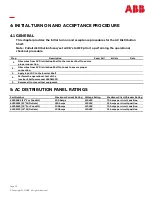
Page 15: ...onnection 2 Ohm wires from AC Distribution Shelf to Loads to ensure proper connection 3 Apply input DC to the Inverter Shelf 4 Perform the operational test of the Inverter Shelf per manual 4380419PD 5 Remove all tools and test equipment 5 AC DISTRIBUTION PANEL RATINGS Part Number Maximum Current Rating Voltage Rating Maximum Circuit Breaker Rating 6180498P 23 For Conduit 200 Amps 120VAC 70 Amps pe...

Page 16: ...t any responsibility whatsoever for potential errors or possible lack of information in this document We reserve all rights in this document and in the subject matter and illustrations contained therein Any reproduction disclosure to third parties or utilization of its contents in whole or in parts is forbidden without prior written consent of ABB Copyright 2021 ABB All rights reserved ABB 601 Shi...

Reviews: