Tension Electronics PFEA111/112, User Manual
Appendix F PFCL 201 - Designing the Load Cell Installation
F-4
3BSE029380R0101 Rev C
F.5 Mounting Alternatives, Calculating Force and Calculating Wrap Gain
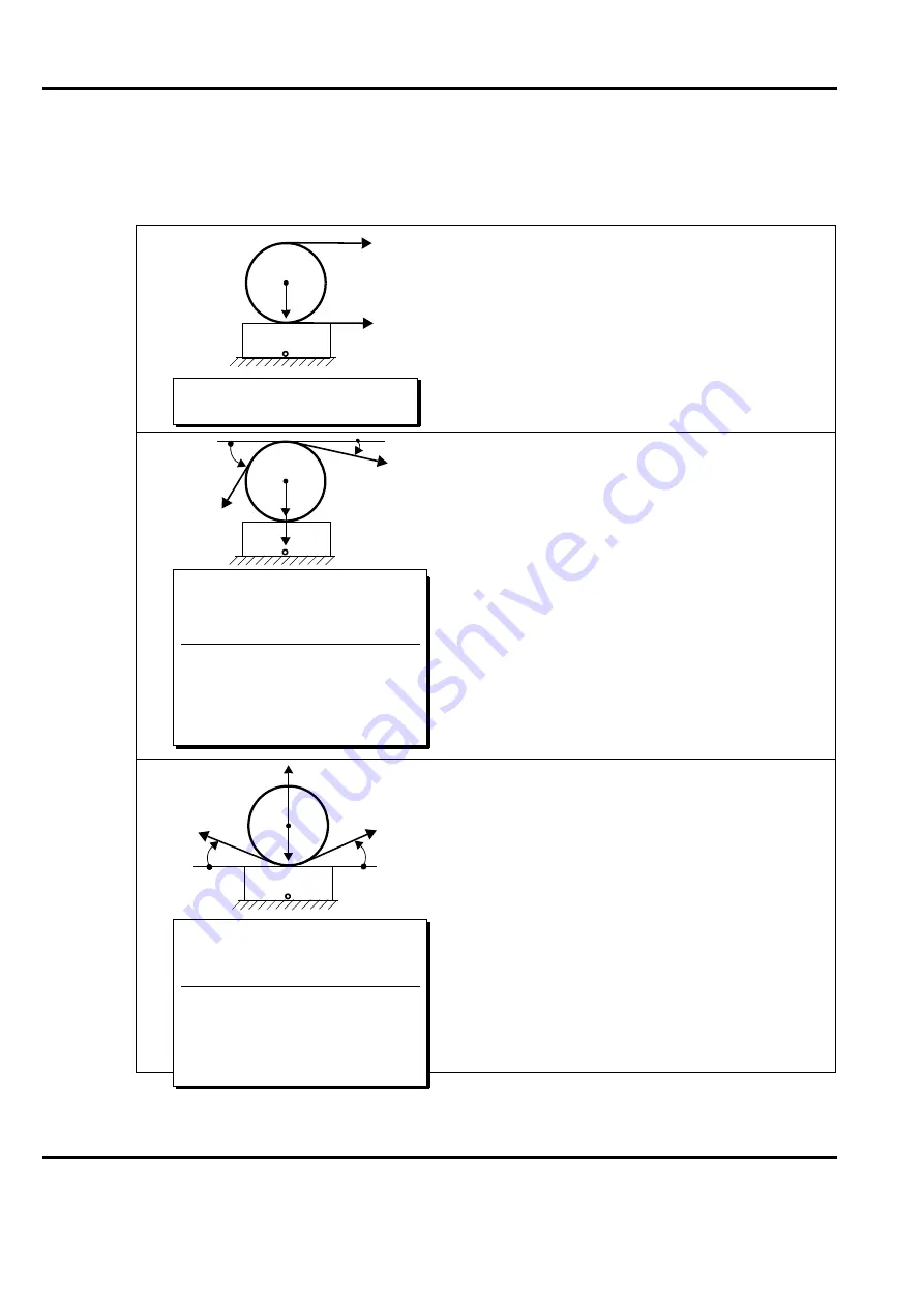
F.5.1 Horizontal Mounting
In most cases, horizontal mounting is the most obvious
and simplest solution. The load cell should thus be
mounted horizontally when possible.
However, should the machine design require inclined
mounting of the load cell or should the web path not give
a sufficient vertical force, see figure, the inclined
mounting is permitted and the calculations are somewhat
more complex, (see
The load cell measures the vertical forces applied to its top
surface. The horizontal applied forces are not measured
and do not influence the vertical measurement. There are
two sources of vertical forces; the forces from the web
tension and the tare weight of the roll.
Divide the total vertical force F
Rtot
by two to get the
required capacity of each load cell.
Do not oversize an ABB load cell for overload purposes
as the load cell has sufficient overload capacity.
The load cell can measure tension as well as compression.
If the T (sin
+
sin
) is larger than the tare weight, the
load cell will be in tension.
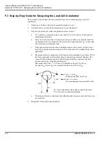
To get the capacity of each load cell:
1. Divide (F
R
- Tare) by two
if F
R
is greater than or equal to (Tare × two).
2. Divide Tare by two
if F
R
is smaller than (Tare × two).
Tare
T
T
No vertical web tension force
applied to the load cell.
PFCL 201
Tare
F
R
T
T
F
R
= T × (sin
+ sin
)
F
Rtot
= F
R
+ F
RT
= T × (sin
+ sin
) + Tare
F
RT
= Tare
Wrap gain
T
FR
--------
T
T
sin
sin
+
----------------------------------------
=
=
Wrap gain
1
sin
sin
+
-------------------------------
=
T (Tension)
Wrap gain
FR
=
Tare
F
R
T
T
F
Rtot
= F
RT
F
R
= Tare
T × (sin
+ sin
)
F
RT
= Tare
F
R
= T × (sin
+ sin
)
Wrap gain
T
FR
--------
T
T
sin
sin
+
----------------------------------------
=
=
Wrap gain
1
sin
sin
+
-------------------------------
=
T (Tension)
Wrap gain
FR
=
Summary of Contents for PFEA 111
Page 30: ...Tension Electronics PFEA111 112 User Manual Chapter 2 Installation 2 14 3BSE029380R0101 Rev C ...
Page 70: ...Tension Electronics PFEA111 112 User Manual Chapter 4 Operation 4 6 3BSE029380R0101 Rev C ...
Page 72: ...Tension Electronics PFEA111 112 User Manual Chapter 5 Maintenance 5 2 3BSE029380R0101 Rev C ...
Page 215: ......


