Tension Electronics PFEA111/112, User Manual
Section 3.9 Checking Load Cell Signal Polarity
3BSE029380R0101 Rev C
3-9
3.9 Checking Load Cell Signal Polarity
This is a simple method to check that the load cells are connected to give a positive output
signal change from the tension electronics for increased web tension.
1.
Push with your hand to apply a force corresponding to increased web tension on one load
cell at a time (as close to the load cell as possible) and check if the display reading is
positive. If the display reading is negative, invert the load cell signal connection to the
tension electronics.
NOTE
If you don’t know in which direction the force is acting,
connect load cell A and B with the same force direction.
To change the polarity of load cell A, invert X1:5 and 6 (In A+ and In A-).
To change the polarity of load cell B, invert X1:9 and 10 (In B+ and In B-).
2.
After changing load cell polarity, check that the display reading is positive for increased
web tension.
3.10 Checking Load Cell Function
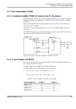
The “Hanging Weight” procedure can also be used as a function test on load cells,
see
.
The rope should then be placed in the web path but as close as possible to one of the
load cells. The output signal should be noted, and the rope moved close to the other
load cell. Check that the difference in output signal is small.
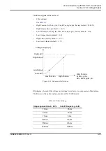
Figure 3-2. Load Cell Function Test
15
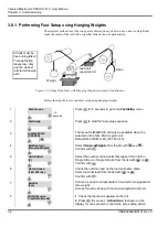
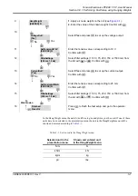
Select filter settings (15, 30, 75, 250, 750 or 1500 ms) from
the list with
or
. Confirm with
.
16
Press
to finish the fast setup and go to the operator
menu.
FilterSettings
[250 ms 1.5 Hz]
To
WebTension
Finished
PressOk
Summary of Contents for PFEA 111
Page 30: ...Tension Electronics PFEA111 112 User Manual Chapter 2 Installation 2 14 3BSE029380R0101 Rev C ...
Page 70: ...Tension Electronics PFEA111 112 User Manual Chapter 4 Operation 4 6 3BSE029380R0101 Rev C ...
Page 72: ...Tension Electronics PFEA111 112 User Manual Chapter 5 Maintenance 5 2 3BSE029380R0101 Rev C ...
Page 215: ......


