Tension Electronics PFEA111/112, User Manual
Chapter 3 Commissioning
3-16
3BSE029380R0101 Rev C
3.12.5 Set Wrap Gain
To be able to present actual web tension on the display, the ratio between web tension and
measured force on the load cell must be determined.
This ratio is a scaling factor called Wrap Gain.
The Wrap Gain depends on the web's wrap angle on the measuring roll and the orientation of the
load cells. Therefore, Wrap Gain depends on the actual installation.
This gives:
T
(tension)
= Wrap Gain
F
R
(force of web tension in load cell measuring direction)
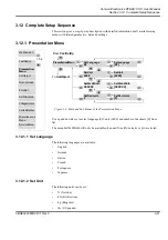
Figure 3-10. Wrap Gain Menus
There are two ways to find out the ratio between web tension and measured force on the load
cells, by Hanging weights or by Calculation.
•
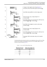
With hanging weights (
Menu
HangWeight
)
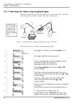
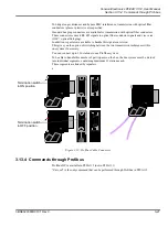
String a rope that follows the web path exactly and apply a known weight.
The applied known weight simulates the actual web tension and the electronics measures
the resulting force on the load cells caused by the applied weight.
When both web tension (T) and the corresponding measured force (F
R
) are known the
tension electronics calculates the ratio T / F
R
and stores the value as Wrap Gain.
When web tension is applied to the roll the tension electronics calculates web tension by
multiplying the measured force on the load cells with the Wrap Gain.
After the hanging weight procedure the wrap gain calculated by the tension electronics can
be found in the EnterWrapGain menu.
Figure 3-11. Setting Wrap Gain with Hanging Weights (example of installation)
SetObject
Fast SetUp
WebTension
Presentation-
Menu
NominalLoad
ServiceMenu
ZeroSet
SetWrapGain
> 5 s
Current Output
Voltage Output
Miscellaneous
Menu
SetWrapGain
HangWeight
XXXXXX.X N
EnterWrapGain
XX.XX
HangWeight
[XXXXXX.X] N
EnterWrapGain
[XX.XX]
From
ZeroSet
To
VoltageOutput
Load cell
Weight
Rope
supported roll
All rolls must be
free turning idlers.
To keep friction
losses low, only
use the closest
rolls to define web
path.
Summary of Contents for PFEA 111
Page 30: ...Tension Electronics PFEA111 112 User Manual Chapter 2 Installation 2 14 3BSE029380R0101 Rev C ...
Page 70: ...Tension Electronics PFEA111 112 User Manual Chapter 4 Operation 4 6 3BSE029380R0101 Rev C ...
Page 72: ...Tension Electronics PFEA111 112 User Manual Chapter 5 Maintenance 5 2 3BSE029380R0101 Rev C ...
Page 215: ......

