background image

Tension Electronics PFEA111/112, User Manual

Section D.6 Mounting Alternatives, Calculating Force and Calculating Wrap Gain

3BSE029380R0101 Rev C

D-5

D.6 Mounting Alternatives, Calculating Force and Calculating Wrap Gain

D.6.1 Horizontal Mounting

The PFRL 101 load cells can be mounted at any incline 
angle, 0 - 360°. However, it is recommended to minimize 
the influence of forces other than the tension to be 
measured. In most cases this means an orientation where 
the tare force (vertical) is perpendicular to the measured 
force (horizontal).
However, should the machine design require inclined 
mounting of the load cell or should the web path not give 
a sufficient horizontal force, see figure, the inclined 
mounting is permitted and the calculations are somewhat 
more complex, (see 

Section D.6.2, Inclined Mounting

).

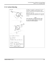
The load cell measures the horizontal forces. The load 
cell can measure in both directions. The vertical applied 
forces are not measured and do not influence the 
horizontal measurement. There is one source of 
horizontal forces, the force from the web tension (the tare 
weight has no force component in measuring direction). 
See force calculations in figure.
Divide the total vertical force F

Rtot

 by two to get the 

required capacity of each load cell.
Do not oversize an ABB load cell for overload purposes 
as the load cell has sufficient overload capacity.

No horizontal web tension force 
applied to the load cell.

Tare

T

T

F

 = T × (cos 


 cos 

)

F

Rtot 

= F

R

 + F

RT 

= T × (cos 


 cos 

)

F

RT 

= 0 (Tare force is not measured)

T

T

F

R

Tare

+

+

Horizontal plane

F

Rtot 

/ load cell =  F

Rtot 

/ 2

Wrap gain

T

FR

--------

T

T

cos

cos

------------------------------------------

=

=

Wrap gain

1

cos

cos

---------------------------------

=

T (Tension)

Wrap gain

FR

=

Summary of Contents for PFEA 111

Page 1: ... ABB MEASUREMENT ANALY TICS Web Tension Systems with Tension Electronics PFEA 111 112 User Manual 3BSE029380R0101 en Rev C ...

Page 2: ...f any nature or kind arising from the use of this document nor shall ABB AB be liable for incidental or consequential damages arising from use of any software or hardware described in this document This document and parts thereof must not be reproduced or copied without ABB AB s written permission and the contents thereof must not be imparted to a third party nor be used for any unauthorized purpo...

Page 3: ... the Electronic Unit 2 2 2 4 1 Selecting and Routing the Cabling 2 2 2 4 1 1 Recommended Cabling 2 2 2 4 1 2 Interference 2 4 2 4 1 3 Synchronization 2 4 2 4 2 Mounting the Tension Electronics PFEA111 112 2 5 2 4 2 1 IP 65 version NEMA 4 2 5 2 4 2 2 IP 20 version Unsealed 2 7 2 4 3 Earthing 2 8 2 5 Installing MNS Select Floor Cabinet 2 9 2 5 1 Mounting Cabinets Together 2 9 2 5 2 Mounting Cabinets...

Page 4: ...th 3 12 3 12 1 4 Set Decimals 3 12 3 12 2 Set Object 3 13 3 12 3 Nominal Load 3 14 3 12 4 Zero Set 3 15 3 12 5 Set Wrap Gain 3 16 3 12 6 Voltage Output 3 18 3 12 7 Current Output 3 20 3 12 8 Miscellaneous Menu 3 22 3 12 8 1 Profibus 3 22 3 12 8 2 Set Factory Default 3 22 3 12 9 Service Menu 3 23 3 12 9 1 Maximum Load Present Offset 3 24 3 12 9 2 Reset A B 3 24 3 12 9 3 Simulation function 3 24 3 1...

Page 5: ...l two load cells 4 5 4 7 1 2 Single Side A or Single Side B measurement one load cell 4 5 4 7 2 Error and Warning Messages 4 5 Chapter 5 Maintenance 5 1 About this Chapter 5 1 5 2 Preventive Maintenance 5 1 Chapter 6 Fault tracing 6 1 About this Chapter 6 1 6 2 Safety Instructions 6 1 6 3 Interchangeability 6 2 6 4 Necessary Equipment and Documentation 6 2 6 5 Fault tracing Procedure 6 3 6 6 Error...

Page 6: ...v A A 11 A 7 Profibus DP GSD File for PFEA112 A 12 Appendix B PFCL 301E Designing the Load Cell Installation B 1 About This Appendix B 1 B 2 Basic Application Considerations B 1 B 3 Step by Step Guide for Designing the Load Cell Installation B 2 B 4 Installation Requirements B 3 B 5 Mounting Alternatives Calculating Force and Calculating Wrap Gain B 4 B 5 1 Horizontal Mounting B 4 B 5 2 Inclined M...

Page 7: ...ng 3BSE019040D0094 Rev C C 13 C 12 Assembly Drawing 3BSE019040D0096 Rev C C 14 Appendix D PFRL 101 Designing the Load Cell Installation D 1 About This Appendix D 1 D 2 Basic Application Considerations D 1 D 3 Step by Step Guide for Designing the Load Cell Installation D 2 D 4 Installation Requirements D 3 D 5 Load Cell Orientation Depending on Measurement Direction D 4 D 6 Mounting Alternatives Ca...

Page 8: ...ll E 7 E 7 Mounting the Load Cells E 8 E 7 1 Routing the Load Cell Cable E 9 E 8 Technical Data E 10 E 9 Cable Diagram 3BSE028140D0065 Page 3 5 Rev C E 12 E 10 Cable Diagram 3BSE028140D0065 Page 4 5 Rev C E 13 E 11 Cable Diagram 3BSE028140D0065 Page 5 5 Rev C E 14 E 12 Dimension Drawing 3BSE004171 Rev B E 15 E 13 Dimension Drawing 3BSE004995 Rev C E 16 E 14 Dimension Drawing 3BSE023301D0064 Rev B ...

Page 9: ...awing 3BSE006699D0005 Rev J F 18 F 15 Dimension Drawing 3BSE006699D0004 Rev H F 19 Appendix G PFTL 201 Designing the Load Cell Installation G 1 About This Appendix G 1 G 2 Basic Application Considerations G 1 G 3 Step by Step Guide for Designing the Load Cell Installation G 2 G 4 Installation Requirements G 3 G 5 Mounting Alternatives Calculating Force and Calculating Wrap Gain G 4 G 5 1 Horizonta...

Page 10: ...ENTS continued G 13 Dimension Drawing 3BSE008724 Rev F G 17 G 14 Dimension Drawing 3BSE008905 Rev G G 18 G 15 Dimension Drawing 3BSE008917 Rev H G 19 G 16 Dimension Drawing 3BSE008918 Rev G G 20 Appendix H Actual Data and Settings at Commissioning H 1 Document the Commissioning in this Form F 1 ...

Page 11: ...ed to installation of firewalls application of authentication measures encryption of data installation of antivirus programs etc to protect the product and the network its system and interface included against any kind of security breaches unauthorized access interference intrusion leakage and or theft of data or information ABB is not liable for any such damages and or losses 1 3 WEEE Waste Elect...

Page 12: ...zontal force sensing load cell PFTL 201 Appendix G Each appendix contains detailed information about one of the above load cell types when used in web tension systems with Tension Electronics PFEA111 112 1 4 1 Getting Started You can use the Fast Setup sequence to set up your system for basic measurement The Fast Setup guides you through a minimum number of steps to set up the tension electronics ...

Page 13: ...k the status of the tension system The 2 x 16 character display can present sum difference or individual load cell signals All three versions are available in both DIN rail version IP 20 version unsealed and enclosed IP 65 version NEMA 4 for mounting in more severe environments Load cells of type PFCL 201 PFCL 301E PFTL 101 PFTL 201 PFTL 301E and PFRL 101 The equipment is intended for use in a wid...

Page 14: ...k switch off and lock the operating switch of the drive section for the measuring roll DANGER Switch off and lock the mains operating switch to the tension electronics before performing any work on the tension electronics When the work is completed check that there are no loose wires and that all units are properly secured NOTE All personnel working with the installation must know the location of ...

Page 15: ... a magnetic field Unlike other types of load cell technologies physical movement such as compression bending or stretching is not required for signal generation A Pressductor transducer the sensor inside the load cell is a simple and elegant design Essentially two perpendicular windings of copper wire around a steel core combine to provide a measurement signal An electromagnetic field is created b...

Page 16: ...Tension Electronics PFEA111 112 User Manual Chapter 1 Introduction 1 6 3BSE029380R0101 Rev C Figure 1 2 The Sensor Based on Pressductor Technology ...

Page 17: ...ment which although intended for severe operating conditions must be handled with care 2 2 Safety Instructions Read and follow the safety instructions given in Chapter 1 before starting any installation work However local statutory regulations if stricter are to take precedence 2 3 Mounting the Load Cells Installation requirements and mounting instructions are given in Appendix B PFCL 301E Designi...

Page 18: ...pendix for your type of load cell or according to order specific documentation Figure 2 1 Recommended Cabling n 0 5 mm2 screen To control system Mains supply 3 1 5 mm2 Junction Box Load cell signals 2 2 0 5 mm2 screen Load cell excitation 2 2 5 mm2 4 1 0 mm2 screen max 50 m Externalindicating instrument not included in the ABB delivery Load cell A Load cell B PFEA111 112 IP 65 version Profibus DP ...

Page 19: ...n electronics signal and excitation must be routed in separate cables For example a 2 2 5 mm2 cable for the excitation and a shielded 2 2 0 5 mm2 cable with twisted pair cores for the load cell signals Cable for synchronization of two of more tension electronics must be screened or a twisted pair The signal cable between the tension electronics and instruments or process equipment must be a screen...

Page 20: ...ot required for the wall mounted IP 65 version NEMA 4 of the tension electronics If two or more IP 20 version unsealed tension electronics are mounted in the same cabinet they must be synchronized Synchronization is done by interconnecting the SYNC terminals screw terminal X1 14 of all the units and interconnecting screw terminal X 15 of all units A twisted pair cable or a screened cable must be u...

Page 21: ...ck that there will be space to open the enclosure lid fully Also check that there is enough working space in front of the enclosure The enclosure is fitted with cable glands PFEA 111 five and PFEA 112 six cable glands Figure 2 4 Installation Dimensions for PFEA 111 112 1 x for cable 6 12 0 24 0 47 Enclosure threaded for NPT 1 2 2 x for cable 6 12 0 24 0 47 2 x for cable 4 8 0 16 0 31 Note To fulfi...

Page 22: ...Connect the cables to terminals according cable diagrams in Appendix B C D E F or G depending on installed load cell type NOTE Do not connect solid conductors to terminals Do not crimp pins to stranded cores NOTE The incoming mains voltage must be provided with fuses and a means of disconnection outside the tension electronics ...

Page 23: ... to the metallic DIN rail which serves as the Tension Electronics earth connector This is to ensure a good earth connection both for internal logic and for the EMI immunity and RF emission of the electronics The DIN rail must have a good connection to the PE Protective Earth of the cabinet To achieve the best possible corrosion resistance DIN rails should be chromium plated for instance yellow chr...

Page 24: ...rth bar and the length of the screen connection must be less than 50 mm 2 in NOTE The cable screens must be earthed at one end only Since the signal earth of the measurement system is connected to the chassis earth of the tension electronics the input of a superior system connected to the control system must not be earthed The best ways of interconnecting the measurement system and a superior syst...

Page 25: ...r Screw Position 2 5 2 Mounting Cabinets to the Floor When fixing the cabinet to the floor use four or six M12 screws where Figure 2 10 indicates one at each corner in the first left hand cabinet in a row of cabinets and screw the following cabinets with two screws each at the right hand side The bottom angle hinges features holes 14 mm 0 6 in diameter These holes permit you to adjust the cabinet ...

Page 26: ...ween the rear of the cabinet and the wall and between the sides of the cabinet and the wall To permit a frame with hinge or a door to an outer encapsulation to open fully without catching on the adjacent wall the distance to the wall must be increased to 500 mm on the hinge side left of the frame or 300 mm on the hinge side right of the door There must be at least 1 meter of free space in front of...

Page 27: ... is long The cables fixed to the load cells and the cable to the control unit are to be connected to the junction box The junction box PFXC 141 shall be mounted adjacent to the load cells and located in a protected position easily accessible for service The dimensions of the junction box are shown in Figure 2 11 Holes not used must be plugged For circuit diagram see Appendix A 5 3 Junction Box PFX...

Page 28: ... 3BSE029380R0101 Rev C 2 7 Connecting the Load Cells Information for connecting the load cells is given in the appendix for each load cell type see table below Type of load cell Cable diagrams in Appendix PFCL 301E B PFTL 301E C PFRL 101 D PFTL 101 E PFCL 201 F PFTL 201 G ...

Page 29: ...tronics If PXUB 201 is mounted close to the terminal group it is not necessary for the cable between the tension electronics and PXUB 201 to be screened Figure 2 12 Typical Connection of Insulation Amplifier PXUB 201 2 8 2 Power Supply Unit SD83x If no 24 V is available the power supply units SD 831 SD 832 and SD 833 can be used as power supply for the IP 20 versions The power supply unit is inten...

Page 30: ...Tension Electronics PFEA111 112 User Manual Chapter 2 Installation 2 14 3BSE029380R0101 Rev C ...

Page 31: ... the following data before starting commissioning 1 Load cell type and nominal load see Appendix for installed load cell type 2 Object type see Section 3 12 2 Standard roll two load cells Single side measurement one load cell 3 Maximum web tension 4 Desired output data at given web tension 5 Communication data see Section 3 13 3 2 Safety Instructions Read and follow the safety instructions stated ...

Page 32: ...l not be stored If is pressed the old value is displayed without brackets To change a numerical value press so that the value is placed within brackets Then the first digit can be changed with and When the first digit has the desired value press then the second digit can be changed with and When pressing after the last digit has been set the new value is saved and displayed without brackets Using ...

Page 33: ...not shown in this overview In these menus you have to confirm that your settings should be performed VoltageOutput See 3 12 6 5 CurrentOutput See 3 12 7 The fast setup can be made in two ways depending on how the wrap gain is set Language Unit Web width4 and desired number of decimals are set in the presentation menu Select standard roll 2 load cells single side A or single side B measurement Chec...

Page 34: ...the cable diagrams Appendix B C D E F or G 3 Check the supply voltage 3 7 DIN rail mounted IP20 unit unsealed Nominal 24 V DC Working range 18 36 V DC X1 1 2 Wall mounted IP65 unit NEMA 4 85 264 V AC 100 V 15 to 240 V 10 45 65 Hz X9 1 2 Nominal 24 V DC Working range 18 36 V DC X1 1 2 4 Perform basic settings if necessary 3 7 5 Perform setup Fast setup 3 8 Complete setup 3 11 6 Check load cell sign...

Page 35: ...etup All other parameters are set as factory default values See Appendix A 4 Factory Default Settings The fast setup can be made in two ways depending on how the wrap gain is set The wrap gain can be set by selecting HangWeight or EnterWrapGain Using Hanging Weights see Section 3 8 1 Using Wrap Gain see Section 3 8 2 Hanging Weights and Wrap Gain are explained in Section 3 12 5 1 Select desired la...

Page 36: ...ct HangingWeights from the list with and Confirm with 5 Select the number of load cells that support the roll 2 or Single Side A or Single Side B from the list with or Confirm with 6 Check the nominal load on the load cell name plate Select nominal load from the list with or Confirm with 7 Zero set is used to compensate for load cell zero signal and tare weight Zero set must be done with no tensio...

Page 37: ...0 V Confirm with 12 Select filter settings 15 30 75 250 750 or 1500 ms from the list with or Confirm with 13 Select Yes and press to set up the current output Confirm with 14 Enter the tension value corresponding to 20 mA Confirm with 15 Select filter settings 15 30 75 250 750 or 1500 ms from the list with or Confirm with 16 Press to finish the fast setup and go to the operator menu Table 3 1 Unit...

Page 38: ...e with no tension applied to the roll 8 1 Check that no load is applied on the roll 2 Press to zero set ActionDone is shown on the display for one second to confirm the zero setting action 9 Enter the calculated wrap gain For calculating wrap gain see Appendix B C D E F or G for installed load cell type Confirm with 10 Select Yes and press to set up the voltage output 11 Enter the tension value co...

Page 39: ... and B with the same force direction To change the polarity of load cell A invert X1 5 and 6 In A and In A To change the polarity of load cell B invert X1 9 and 10 In B and In B 2 After changing load cell polarity check that the display reading is positive for increased web tension 3 10 Checking Load Cell Function The Hanging Weight procedure can also be used as a function test on load cells see S...

Page 40: ...d B or Single side measurement load cell A or B 3 12 2 Set nominal load 3 12 3 Zero set load cells 3 12 4 Set hanging weights actual force or Set wrap gain calculated value 3 12 5 Set filter settings Set high tension value and high output voltage Set low tension value and low output voltage Set high and low output voltage limit 3 12 6 Set filter settings Set high tension value and high output curr...

Page 41: ... decimals Z from list The menu SetWebWidth will only be available when unit N m kN m kg m or pli is selected 3 12 1 1 Set Language The following languages are available English German Italian French Portuguese Japanese 3 12 1 2 Set Unit The following units can be set N Newton kN kiloNewton kg kilogram lbs US pounds SetObject FastSetUp WebTension Presentation Menu NominalLoad ServiceMenu ZeroSet Se...

Page 42: ...he menu SetWebWidth will only be available when the selected unit is N m kN m kg m or pli Default Web Width is 2m 78 740 inch The format is XX XXX if the width is entered in meter and XXXX XX if the width is entered in inch Maximum Web Width is 50m 1968 5 inch 3 12 1 4 Set Decimals The number of displayed decimals can be set in this menu The number of decimals may be set to a number between 0 5 de...

Page 43: ... only load cell B is connected to the roll Figure 3 7 Object Type Single Side B measurement When Single Side A or Single Side B measurement is selected the measured signal is multiplied by two and presented as web tension on display and analog output SetObject FastSetUp WebTension Presentation Menu NominalLoad ServiceMenu ZeroSet SetWrapGain 5 s CurrentOutput VoltageOutput Miscellaneous Menu SetOb...

Page 44: ...ate The load cell nominal load is displayed in kN and lbs on the same row The following nominal loads can be selected Table 3 2 Nominal Loads kN lbs 0 1 22 0 2 45 0 5 112 1 0 225 2 0 450 5 0 1125 10 2250 20 4500 50 11250 100 22500 200 45000 SetObject FastSetUp WebTension Presentation Menu NominalLoad ServiceMenu ZeroSet SetWrapGain 5 s CurrentOutput VoltageOutput Miscellaneous Menu NominalLoad ZZ ...

Page 45: ...re weight The zero setting range is 2 x Fnom load cell nominal load Figure 3 9 Zero Set Menus NOTE Zero set must be done with no tension applied to the roll SetObject FastSetUp WebTension Presentation Menu NominalLoad ServiceMenu ZeroSet SetWrapGain 5 s CurrentOutput VoltageOutput Miscellaneous Menu ZeroSet AreYouSure ActionDone shown for 1 s From NominalLoad To SetWrapGain ...

Page 46: ...es the actual web tension and the electronics measures the resulting force on the load cells caused by the applied weight When both web tension T and the corresponding measured force FR are known the tension electronics calculates the ratio T FR and stores the value as Wrap Gain When web tension is applied to the roll the tension electronics calculates web tension by multiplying the measured force...

Page 47: ... outside this range the message WrapGainTooLow or WrapGainTooHigh will be shown on the display The wrap gain can be set with a resolution of 0 01 Examples describing the principle of calculating Wrap Gain See calculation of Wrap Gain in Appendix B C D E F or G for installed load cell type T T T T T T FR FR FR FR 2T FR T FR T Installations where FR is lower than T Wrap angle Wrap angle Wrap gain 0 ...

Page 48: ...viceMenu ZeroSet SetWrapGain 5 s CurrentOutput VoltageOutput Miscellaneous Menu From SetWrapGain To VoltageOutput FilterSettings ZZ ms ZZ Hz HighTension XXXXXX X N HighOutput XX XX V LowOutput XX XX V LowTension XXXXXX X N LowLimit XX XX V HighLimit XX XX V FilterSettings ZZ ms ZZ Hz HighTension XXXXXX X N HighOutput XX XX V LowOutput XX XX V LowTension XXXXXX X N LowLimit XX XX V HighLimit XX XX ...

Page 49: ...y default 0 V High Limit factory default 11 V Low Limit factory default 5 V Figure 3 13 Parameter Definitions Filtering may be used if the voltage output signal is too fast or to compensate roll imbalance The filters are of type linear phase maximum flat 20 dB decade Table 3 3 Filter Settings Step response time 0 90 Cut off frequency 3dB 15 ms 35 Hz 30 ms 15 Hz 75 ms 5 Hz 250 ms 1 5 Hz 750 ms 0 5 ...

Page 50: ...u ZeroSet SetWrapGain 5 s CurrentOutput VoltageOutput Miscellaneous Menu From VoltageOutput To CurrentOutput FilterSettings ZZ ms ZZ Hz HighTension XXXXXX X N HighOutput XX XX mA LowOutput XX XX mA LowTension XXXXXX X N LowLimit XX XX mA HighLimit XX XX mA FilterSettings ZZ ms ZZ Hz HighTension XXXXXX X N HighOutput XX XX mA LowOutput XX XX mA LowTension XXXXXX X N LowLimit XX XX mA HighLimit XX X...

Page 51: ... default 4 mA High Limit factory default 21 mA Low Limit factory default 0 mA Figure 3 15 Parameter Definitions Filtering may be used if the current output signal is too fast or to compensate roll imbalance The filters are of type linear phase maximum flat 20 dB decade Table 3 4 Filter Settings Step response time 0 90 Cut off frequency 3dB 15 ms 35 Hz 30 ms 15 Hz 75 ms 5 Hz 250 ms 1 5 Hz 750 ms 0 ...

Page 52: ...2 Set Factory Default Set factory default The parameters are set as on delivery except Maximum load A and Maximum load B Read more in Appendix A 4 Factory Default Settings SetObject FastSetUp WebTension Presentation Menu NominalLoad ServiceMenu ZeroSet SetWrapGain 5 s CurrentOutput VoltageOutput Miscellaneous Menu From CurrentOutput To Miscellaneous Menu Profibus On Off ZZ ProfibusAddress ZZ Profi...

Page 53: ...ce last reset Present offset B Displays zero offset at last zero set Parameters that can be set Reset A This action sets Maximum load A to zero Reset B This action sets Maximum load B to zero Simulation Activate deactivate simulation function SetObject FastSetUp WebTension Presentation Menu NominalLoad ZeroSet SetWrapGain 5 s CurrentOutput VoltageOutput Miscellaneous Menu ServiceMenu From Miscella...

Page 54: ... function Simulation can be set to ON or OFF If simulation is set to ON the parameters PercentOfFnomA and PercentOfFnomB will be displayed PercentOfFnomB is not shown if Single side A has been selected in ObjectType and PercentOfFnomA is not shown if Single side B has been selected in ObjectType The parameter PercentOfFnom can be set between 100 and 200 in steps of one When simulation is set to ON...

Page 55: ...oing on with a fixed time interval even when no new data is available from the PFEA112 Each slave has an address in the range 0 to 125 Profibus requires that the message format communication parameters and error codes of slaves are made available in a so called type file also known as GSD file See Appendix A 7 Profibus DP GSD File for PFEA112 This file is then stored in the Profibus Master At star...

Page 56: ...ombination is as shown in Figure 3 18 so that a defined idle state potential is ensured on the line Table 3 5 Line Parameters Parameter Line type A Line type B Avoid if possible Impedance in 135 to 165 100 to 130 Capacitance per unit length pF m 30 60 Loop resistance km 110 Core diameter mm 0 64 0 53 Core cross section mm2 0 34 0 22 Table 3 6 Maximum Cable Lengths per Segment Maximum bus segment l...

Page 57: ...able to handle this signal conversion This gives you the option of switching between the two transmission techniques within one system if necessary You can connect up to 126 stations to one Profibus system To be able to handle this number of participants on the bus the bus system must be divided into individual segments containing maximum 32 stations each These segments are linked by repeaters x 3...

Page 58: ...For scaling of Profibus measurement values see Section 3 13 5 2 Each measurement value has 16 bit 2 complement representation Integer 16 3 13 5 1 Miscellaneous Meny Use this menu for scaling Profibus measuring values Figure 3 20 Profibus Scaling SetObject FastSetUp WebTension Presentation Menu NominalLoad ServiceMenu ZeroSet SetWrapGain 5 s CurrentOutput VoltageOutput Miscellaneous Menu From Curre...

Page 59: ...ells the value of the least significant bit is 0 001 2 1000 2 N Measuring range 5000 2 10 000 N User Defined Scaling The Profibus Measuring Range and Load Division can be adjusted to user needs Profibus Measuring Range Profibus Measuring Range estimated web tension during normal operation is a parameter entered by the user After the user has changed the Measuring Range value changing Load cell nom...

Page 60: ... the Load Division can be adjusted This can be done by setting decreasing MeasuringRange in the Miscellaneous Menu to a value that gives a sufficient Load Division resolution a Measuring Range 9000 N New lower setting on measuring range b New Load Division calculated by PFEA112 2 N New value of least significant bit on Profibus With the setting 9000 N in PFEA112 the Profibus measuring range 0 1550...

Page 61: ...ent representation Integer 16 Boolean in The error or warning is active when the corresponding bit is set to 1 Bit No 0 Flash memory error Bit No 1 EEPROM error Bit No 2 Supply error Bit No 3 Load cell excitation error Bit No 4 Synchronization problem 3 13 5 5 Output Buffer Communication Block from PLC to PFEA112 This section specifies Boolean values in the output buffer communication block Bit No...

Page 62: ...ted inside the unit Figure 3 21 Insulation Amplifier PXUB 201 You must open the insulation amplifier to be able to set the switches S1 and S2 1 Demount the insulation amplifier from the DIN rail Use a screw driver to unload the spring at the bottom of the insulation amplifier 2 Press down the snap locks on both sides of the insulation amplifier 3 Pull the top lid open until you see both the switch...

Page 63: ...ult Range S1 S2 Input Output 1 2 3 1 2 3 0 to 10 V 0 to 10 V 0 to 5 V 4 to 20 mA 0 to 10 V 4 to 20 mA 0 to 5 V 0 to 20 mA 0 10 V 0 20 mA Table 3 9 Setting of Bandwidth Default Bandwidth S2 position 3 ON 10 kHz 10 Hz Earth Earth Signal 0 V 24 V 0 V 5 6 3 4 7 8 Signal 0 V 24 V 0 V 5 6 3 4 7 8 PXUB 201 PXUB 201 1 2 3 ON S1 1 2 3 ON S2 1 2 3 ON S1 1 2 3 ON S2 Output 4 to 20 mA Input 0 to 10 V Output 0...

Page 64: ...Tension Electronics PFEA111 112 User Manual Chapter 3 Commissioning 3 34 3BSE029380R0101 Rev C ...

Page 65: ...know how to start and shut down the system see Section 4 4 Start up and shut down 4 2 Safety Instructions Read and follow the safety instructions given in Chapter 1 Introduction before starting any operation work However local statutory regulations if stricter are to take precedence 4 3 Operating Devices The LED indicators and operator keys are described in Figure 4 1 Figure 4 1 Operating Devices ...

Page 66: ...ON OFF switch to position ON For the IP 65 version NEMA 4 also set the internal switch to ON 3 Check that the display is illuminated the Power indicator is lit the Status indicator is lit green light Red light indicates an error 4 4 2 Shut down Shut down the tension electronics by setting the external ON OFF switch to position OFF 4 5 Normal Run The measurement equipment should be permanently on t...

Page 67: ... XX 1 kN XXX XXX XXX XXX XX XXX X XX XXX X 2 kN XXX XXX XXX XXX XX XXX X XX XXX X 5 kN XXX XXX XXX XXX XX XXX X XX XXX X 10 kN X XXX XX0 X XXX XX XXX XXX XXX XXX 20 kN X XXX XX0 X XXX XX XXX XXX XXX XXX 50 kN X XXX XX0 X XXX XX XXX XXX XXX XXX 100 kN X XXX X00 X XXX X XXX XX0 X XXX XX0 200 kN X XXX X00 X XXX X XXX XX0 X XXX XX0 Load cell nominal load N m kN m kg m pli 0 1 kN XX XXX XX XX XXXXX X X...

Page 68: ...ues displayed together with the Set Decimals function Example 1 Selected unit pli Load cell nominal load 1 kN Measured value 46 5987 pli Set Decimals 2 Value presented on display 46 60 pli Example 2 Selected unit pli Load cell nominal load 1 kN Measured value 46 5987 pli Set Decimals 0 Value presented on display 47 pli 4 7 Operator Menus This section describes the operator menus The updating time ...

Page 69: ...ted to the tension electronics WebTension Web Tension is displayed for single side measurement Web tension is the tension measured by the connected load cell multiplied by 2 4 7 2 Error and Warning Messages An ERROR is something that causes the tension electronics to function incorrectly A WARNING is something that might affect the accuracy of the measurement When a warning or an error occurs a wa...

Page 70: ...Tension Electronics PFEA111 112 User Manual Chapter 4 Operation 4 6 3BSE029380R0101 Rev C ...

Page 71: ...s Load cells Protect the load cells from prolonged contact with corrosive elements Check the fixing screws and re tighten if necessary Check the gaps between load cell and adapter plates to ensure that they are not clogged with dirt which can cause a shunt force into the load cell Clean the gaps with compressed air if necessary Tension Electronics Check that the circuit boards are properly secured...

Page 72: ...Tension Electronics PFEA111 112 User Manual Chapter 5 Maintenance 5 2 3BSE029380R0101 Rev C ...

Page 73: ...fferent ways and the reason for the fault can be difficult to find However disturbances similar in character can be grouped together and usually they have the same or similar sources of error The fault tracing instructions in this chapter will help you to quickly find and correct the most common faults 6 2 Safety Instructions Read and follow the safety instructions given in Chapter 1 Introduction ...

Page 74: ...x B C D E F or G for installed load cell type Service tools Torque wrench Multimeter Unit Measures Tension Electronics The tension electronics PFEA111 112 is interchangeable with a tension electronics of the same type A new setup is required Load cells The load cells are directly interchangeable with other load cells of the same type Zero setting PFEA111 112 and resetting Maximum Load A or Maximum...

Page 75: ...ess line such as web breakage may cause an overloading large enough to alter load cell data Depending on the amount of overload it may be sufficient to zero set 1 Read more about the overload capacity for your load cell type in Appendix B C D E F or G Cabling Problems such as malfunctions or unstable zero point may arise from faulty cables or wiring Proximity to noisy cables may cause interference...

Page 76: ...from the display If the problem that activated the warning or error message has disappeared the Status indication turns to green If the error or warning remains the Status indication is red Use the to step to the last operator menu where you can read the error or warning message 6 6 1 Error Messages The following errors can be detected Flash memory error EEPROM memory error Supply error Load cell ...

Page 77: ... has diagonal pairs one pair for signal circuit and one par for excitation circuit see Figure 2 2 Check if a junction box is installed that load cell signal and load cell excitation between junction box and electronics are routed in separate cables Check if two or more IP 20 units are mounted close to each other in the same cabinet that they are synchronized cable for synchronizing the units see c...

Page 78: ...f the individual load cells have opposite signs polarity when a force is applied on the middle of the roll To check load cell signal polarity see Section 3 9 Checking Load Cell Signal Polarity For connecting the load cells to give positive signals for increased web tension see cable diagram for the installed load cell type 3 Switch off the tension electronics and measure the cable resistance in th...

Page 79: ...terminals X1 1 and X1 2 should be 18 36 V If the voltage is lower than 18 V Check the power supplies rating Rating should be 18 36 V DC Check that the power supply has sufficient capacity See power requirements in Section 2 8 2 Power Supply Unit SD83x If the power supply has sufficient capacity check cabling and cable resistance between power supply and PFEA111 112 If power supply and cabling are ...

Page 80: ... the resistance between terminals X1 3 and X1 8 The resistance is 8 ohm Check that the total cable resistance between electronics and load cells does not exceed 5 ohm If cable resistance does not exceed 5 ohm check cabling and load cells The resistance is 7 ohm If cabling is correct the electronics is probably defect Replace PFEA111 112 6 8 2 Warnings 6 8 2 1 Profibus Communication Problem Check t...

Page 81: ...shorting wire for the load cell excitation circuit between X1 3 and X1 4 Load cell B is faulty 1 Disconnect load cell B from the Tension Electronics 2 Connect a shorting wire for the load cell excitation circuit between X1 7 and X1 8 After having changed the load cell connections one parameter setting in the Tension Electronics must be changed Use the menu below to change from StandardRoll to Sing...

Page 82: ... cable ends from dirt and damage 3 Clean the old load cell before it is unfastened and removed 4 Unfasten and remove the old load cell 5 Unfasten and remove the adapter plates from the old load cell 6 Clean the support structure adapter plates and other mounting surfaces 7 For mounting instructions for the new load cell see Appendix B PFCL 301E Designing the Load Cell Installation Appendix C PFTL ...

Page 83: ...12 Data for the load cells are given in Appendix B PFCL 301E Designing the Load Cell Installation Appendix C PFTL 301E Designing the Load Cell Installation Appendix D PFRL 101 Designing the Load Cell Installation Appendix E PFTL 101 Designing the Load Cell Installation Appendix F PFCL 201 Designing the Load Cell Installation Appendix G PFTL 201 Designing the Load Cell Installation The definitions ...

Page 84: ...or Linearity deviation is the maximum deviation from a straight line drawn between the output values of zero and nominal load related to the nominal load Hysteresis is the maximum deviation of the output signal at the same load during a cycle from zero to nominal load and back to zero related to the sensitivity at nominal load The hysteresis is proportional to the cycle Repeatability error is defi...

Page 85: ...ed by the context Figure A 1 Coordinate System Defining Directions used in Force Calculations T Web tension Tare Force of tare weight of roll and bearing arrangement mounted on the load cells FR Measured force force component of the web tension in the measuring direction of the load cell FRT Applied force component of tare in the measuring direction of the load cell FRtot Total applied force in th...

Page 86: ...100 V 15 to 240 V 10 Mains frequency 45 65 Hz 100 240 V AC 0 2 0 1 A Power consumption 8 W 24 V Fuse IP 20 unit unsealed IP 65 unit NEMA 4 Automatic reset Slow blow 2 A 250 V Table A 3 Data for Load Cell Excitation Data Comments Current 0 5 A rms 330 Hz Regulated Max load Two load cells max 5 cable resistance 1 F cable capacitance Load cells of type PFCL 301E PFTL 301E PFRL 101 and PFTL 101 PFCL 2...

Page 87: ...h 35 Hz Extra filtering for voltage and current output Filter setting Cut off frequency 30 ms 75 ms 250 ms 750 ms 1500 ms 15 Hz 5 Hz 1 5 Hz 0 5 Hz 0 25 Hz Wrap gain adjustment 0 5 20 Table A 6 Measurement Ranges for the Tension Electronics Type Range 1 1 Fnom Load cell nominal load Zero Setting Range 2 0 Fnom Dynamic Measurement Range including zero set 2 5 Fnom to 3 5 Fnom Table A 7 Communication...

Page 88: ...ng temperature Outside the IP 20 version unsealed and IP 65 version NEMA 4 5 to 55 C 32 131 F Non operating temperature 40 to 70 C 40 158 F Degree of protection DIN rail version Wall mounting unit IP 20 unsealed IP 65 NEMA 4 According to EN 60 529 Table A 9 Dimensions Data Comments Dimensions IP 20 version unsealed IP 65 version NEMA 4 86 x 136 x 58 120 x 180 x 100 Width x Height x Depth Width x H...

Page 89: ...l Standard roll Load cell nominal load 1 0 kN 225 lbs 1 0 kN 225 lbs Wrap gain 1 1 Current output Filter setting 250 ms 250 ms High tension 2000 N 2000 N High output 20 00 mA 20 00 mA Low tension 0 N 0 N Low output 4 00 mA 4 00 mA High limit 21 00 mA 21 00 mA Low limit 0 00 mA 0 00 mA Voltage output Filter setting 250 ms 250 ms High tension 2000 N 2000 N Low tension 0 N 0 N High output 10 00 V 10 ...

Page 90: ...2 Hz 2 VA DC 1 W Current consumption 10 mA external load at 24 V Signal range Input Output 0 10 V 0 10 V 0 10 V 4 20 mA 0 5 V 4 20 mA 0 10 V 0 20 mA 0 5 V 0 20 mA Input resistance 1 M at 10 V input 500 k at 5 V input Max load 10 mA for voltage output 500 for current output Rise time 50 s or 50 ms selectable Ripple 10 mVp p Bandwidth 3 dB 10 kHz or 10 Hz Rated insulation voltage 600 V basic insulat...

Page 91: ...gram for Junction Box PFXC 141 Table A 12 Mains Supply Voltage Data Remarks Mains supply voltage 115 V AC 90 132 V 100 V 10 to 120 V 10 230 V AC 180 264 V 200 V 10 to 240 V 10 Auto select Table A 13 Power Supply Unit Unit Dimensions l x w x d Weight SD831 124 x 35x 102 mm 0 43 kg SD832 124 x 35x 117 mm 0 5 kg SD833 124 x 60x 117 mm 0 7 kg Degree of protection Dimensions l x w x d Weight IP 65 NEMA...

Page 92: ...Tension Electronics PFEA111 112 User Manual Appendix A Technical Data for Tension Electronics PFEA111 112 A 10 3BSE029380R0101 Rev C A 6 Drawings A 6 1 Dimension Drawing 3BSE017052D64 Rev D ...

Page 93: ...Tension Electronics PFEA111 112 User Manual Section A 6 2 Dimension Drawing 3BSE029997D0064 Rev A 3BSE029380R0101 Rev C A 11 A 6 2 Dimension Drawing 3BSE029997D0064 Rev A ...

Page 94: ...UTHOR M Sollander REVISION DATE January 27 2003 Profibus_DP GSD_Revision 2 PRODUCT SPECIFICATION Vendor_Name ABB Automation Techn Products Model_Name Tension Electronics PFEA112 Ident_Number 0x0716 Revision 2 0 Hardware_Release 1 0 Software_Release 1 0 OVERALL PROFIBUS SPECIFICATIONS FMS_supp 0 Protocol_Ident 0 Station_Type 0 Slave_Family 0 HARDWARE CONFIGURATION Implementation_type SPC3 Redundanc...

Page 95: ...upp 1 Min_Slave_Intervall 1 Freeze_Mode_supp 1 Sync_Mode_supp 1 Fail_Safe 0 SUPPORTED BAUDRATES 9 6_supp 1 19 2_supp 1 45 45_supp 1 93 75_supp 1 187 5_supp 1 500_supp 1 1 5M_supp 1 3M_supp 1 6M_supp 1 12M_supp 1 MaxTsdr_9 6 60 MaxTsdr_19 2 60 MaxTsdr_45 45 60 MaxTsdr_93 75 60 MaxTsdr_187 5 60 MaxTsdr_500 100 MaxTsdr_1 5M 150 MaxTsdr_3M 250 MaxTsdr_6M 450 MaxTsdr_12M 800 ...

Page 96: ...echnical Data for Tension Electronics PFEA111 112 A 14 3BSE029380R0101 Rev C DIAGNOSTIC DEFINITIONS Max_Diag_Data_Len 6 PARAMETER DEFINITIONS User_Prm_Data_Len 3 User_Prm_Data 0 0 0 MODULE DEFINITIONS Modular_Station 0 Module PFEA112 0x51 0x11 0x21 EndModule ...

Page 97: ...c Application Considerations Each application has its own individual demands that have to be considered though a few basic considerations tend to repeat themselves What type of process is involved papermaking converting etc Is the environment demanding temperature chemicals etc What is the tension measurement purpose indication or closed loop control Are there any specific accuracy demands involve...

Page 98: ...l load c If the span between maximum and minimum tension in the process is large select load cell so that the maximum tension will be in the load cell extended range when applicable d The measured force component of web tension is recommended to be at least 30 of tare force component roll weight acting in load cell measurement direction The reason for this recommendation is load cell signal stabil...

Page 99: ...ntended Shims may be placed between the upper adapter plate and the bearing housing b Follow the manufacturer s recommendation Web and between the lower adapter for other screws for the adapter plates is 24 Nm 18 ft lb If the measuring roll is driven always consult ABB to ensure 0 1 mm 0 004 in Alignment of the load cells Grade G 2 5 ISO 1940 1 that fulfills at least measuring roll of disturbances...

Page 100: ...vertical measurement There are two sources of vertical forces the forces from the web tension and the tare weight of the roll Divide the total vertical force FRtot by two to get the required capacity of each load cell Do not oversize an ABB load cell for overload purposes as the load cell has sufficient overload capacity A PFCL 301E load cell can measure tension as well as compression If the T sin...

Page 101: ...n an incline due to mechanical design constraints of the machine or the need to have a proper force component applied to the load cell In this case the incline angle modifies the tare load and the force components as shown FR T sin sin FRtot FR FRT FRT Tare cos Tare FRT FR T T T sin sin Tare cos PFCL 301E Wrap gain T F R T T sin sin T Tension Wrap gain F R Wrap gain 1 sin sin ...

Page 102: ...vious and simple solution is horizontal mounting with the web evenly distributed and centered on the roll As long as the roll is supported at both ends the same calculations given in Section B 5 Mounting Alternatives Calculating Force and Calculating Wrap Gain are valid NOTE The accuracy of a single load cell measurement is highly dependent on how well the center of force can be determined Since t...

Page 103: ...oad cell centerline Calculation procedure 1 Horizontal or inclined mounting 2 Calculate FR and FRT see Section B 5 Mounting Alternatives Calculating Force and Calculating Wrap Gain 3 Use the following equations FR for single load cell FRT for single load cell FRtot for single load cell FR for single load cell FRT for single load cell where L Distance between load cell centerline and the opposite b...

Page 104: ...ws included in delivery with a torque wrench to 24 Nm 18 ft lb 5 Fit the bearing housing and the roll to the upper adapter plate but do not fully tighten the screws CAUTION When mounting bearings or other adjacent details to adapter plates screws must not protrude into the load cell The load cell can be damaged by an excessive applied force 6 Adjust the load cells according to the installation req...

Page 105: ... permanent change of data Fmax 1 0 6 135 1 5 337 3 674 kN lbs Max load in transverse direction without permanent change of data FVmax 1 For h 135 mm 5 3 inch 1 Fmax and FVmax are allowed at the same time 0 3 67 0 75 169 1 5 337 Spring constant 9 52 22 124 34 197 kN mm 1000 lbs inch Accuracy Accuracy class compressive force 1 0 Linearity deviation 0 5 Repeatability error 0 1 Hysteresis 0 3 Mechanic...

Page 106: ...nt drift 150 83 ppm K ppm F Sensitivity drift 250 139 Working temperature range 10 80 14 176 C F Zero point drift 250 139 ppm K ppm F Sensitivity drift 350 194 Storage temperature range 40 90 40 194 C F Degree of protection IP 66 acc to EN 60 529 Table B 2 Mounting screws Type of screws Strength class Dimension Tightening torque Electro zincplated steel screws lubricated with oil or emulsion Stren...

Page 107: ...Tension Electronics PFEA111 112 User Manual Section B 9 Cable Diagram 3BSE028140D0065 page 2 5 Rev C 3BSE029380R0101 Rev C B 11 B 9 Cable Diagram 3BSE028140D0065 page 2 5 Rev C ...

Page 108: ...Tension Electronics PFEA111 112 User Manual Appendix B PFCL 301E Designing the Load Cell Installation B 12 3BSE029380R0101 Rev C B 10 Mounting Instruction Cable Connector 3BSE019064 Rev A ...

Page 109: ...ev tabel on rev C 2013 02 25 PAMP FMGF LEN C ABB AB 2013 02 25 Cont sh No of sh Sheet Lang Rev Project or order number Modify date Document number Appr Prep Resp dept Product type designation Product information Product family 2013 02 25 10 32 06 661230 Bansp mätare PRT100 ABB AB Håkan F Wintzell 2013 02 25 Lars Erik Nilsson 1 1 D en Lastcell PFCL301E Load Cell PFCL301E Dimension drawing 3BSE01595...

Page 110: ...in Solid Works and uppdated Cable min bending radius added 2013 02 25 PAMP FMGF LEN C ABB AB 2013 02 25 Cont sh No of sh Sheet Lang Rev Project or order number Modify date Document number Appr Prep Resp dept Product type designation Product information Product family 2013 02 25 10 13 18 PFCL 301E 661230 Bansp mätare PRT100 ABB AB Håkan F Wintzell 2013 02 25 Lars Erik Nilsson 1 1 C en Assembly PFCL...

Page 111: ...c Application Considerations Each application has its own individual demands that have to be considered though a few basic considerations tend to repeat themselves What type of process is involved papermaking converting etc Is the environment demanding temperature chemicals etc What is the tension measurement purpose indication or closed loop control Are there any specific accuracy demands involve...

Page 112: ... load c If the span between maximum and minimum tension in the process is large select load cell so that the maximum tension will be in the load cell extended range when applicable d The measured force component of web tension is recommended to be at least 30 of tare force component roll weight acting in load cell measurement direction The reason for this recommendation is load cell signal stabili...

Page 113: ...ntended Shims may be placed between the upper adapter plate and the bearing housing Follow the manufacturer s recommendation and between the lower adapter for other screws for the adapter plates is 24 Nm 18 ft lb If the measuring roll is driven always consult ABB to ensure 0 1 mm 0 004 in Alignment of the load cells Grade G 2 5 ISO 1940 1 that fulfills at least measuring roll of disturbances a sol...

Page 114: ...ll measures the horizontal forces applied to its top surface The load cell can measure in both directions The vertical applied forces are not measured and do not influence the horizontal measurement There is one source of horizontal forces the force from the web tension the tare weight has no force component in measuring direction See the force calculations in the figure Divide the total horizonta...

Page 115: ...force component applied to the load cell Inclined mounting adds a component of tare force in the measuring direction and modifies the force components as shown NOTE When calculating it is important that the angles are set into the equations with the correct signs in relation to the horizontal plane PFTL 301E FR T cos cos FRtot FR FRT FRT Tare sin Tare FRT FR T T T cos cos Tare sin Wrap gain T F R ...

Page 116: ...vious and simple solution is horizontal mounting with the web evenly distributed and centered on the roll As long as the roll is supported at both ends the same calculations given in Section C 5 Mounting Alternatives Calculating Force and Calculating Wrap Gain are valid NOTE The accuracy of a single load cell measurement is highly dependent on how well the center of force can be determined Since t...

Page 117: ...ell centerline see figure Calculation procedure 1 Horizontal or inclined mounting 2 Calculate FR and FRT see Section C 5 Mounting Alternatives Calculating Force and Calculating Wrap Gain 3 Use the following equations FR for single load cell FRT for single load cell FRtot for single load cell FR for single load cell FRT for single load cell where L Distance between load cell centerline and the oppo...

Page 118: ...ten the screws included in delivery with a torque wrench to 24 Nm 18 ft lb 5 Fit the bearing housing and the roll to the upper adapter plate but do not fully tighten the screws CAUTION When mounting bearings or other adjacent details to adapter plates screws must not protrude into the load cell The load cell can be damaged by an excessive applied force 6 Adjust the load cells according to the inst...

Page 119: ... 3 inch 0 3 67 0 6 135 1 5 337 3 0 674 kN lbs Max load in transverse direction without permanent change of data FVmax 1 1 Fmax and FVmax are allowed at the same time 0 5 112 1 0 225 2 5 562 5 0 1125 Max load in axial direction without permanent change of data FAmax For h 135 mm 5 3 inch 0 5 112 0 5 112 1 0 225 1 0 225 Spring constant 2 11 3 4 22 6 7 39 7 8 44 6 kN mm 1000 lbs inch Accuracy Accurac...

Page 120: ...nt drift 150 83 ppm K ppm F Sensitivity drift 250 139 Working temperature range 10 80 14 176 C F Zero point drift 250 139 ppm K ppm F Sensitivity drift 350 194 Storage temperature range 40 90 40 194 C F Degree of protection IP 66 acc to EN 60 529 Table C 2 Mounting screws Type of screws Strength class Dimension Tightening torque Electro zincplated steel screws lubricated with oil or emulsion Stren...

Page 121: ...Tension Electronics PFEA111 112 User Manual Section C 9 Cable Diagram 3BSE028140D0065 Page 1 5 Rev C 3BSE029380R0101 Rev C C 11 C 9 Cable Diagram 3BSE028140D0065 Page 1 5 Rev C ...

Page 122: ...Tension Electronics PFEA111 112 User Manual Appendix C PFTL 301E Designing the Load Cell Installation C 12 3BSE029380R0101 Rev C C 10 Mounting Instruction Cable Connector 3BSE019064 Rev A ...

Page 123: ...updated Mass added Cable bending radius replace dim 25 mm min 2012 12 14 PA FM GF LEN C ABB AB 2012 12 14 Cont sh No of sh Sheet Lang Rev Project or order number Modify date Document number Appr Prep Resp dept Product type designation Product information Product family 2012 12 13 10 22 49 PFTL 301E 661230 Bansp mätare PRT100 ABB AB Håkan F Wintzell 2012 12 14 Lars Erik Nilsson 1 1 C en Lastcell PF...

Page 124: ...AGB LEN C Redrawn in Solid Works and uppdated Cable min bending radius added 2012 12 14 PA FM GF LEN C ABB AB 2012 12 14 Cont sh No of sh Sheet Lang Rev Project or order number Modify date Document number Appr Prep Resp dept Product type designation Product information Product family 2012 12 13 09 25 13 PFTL 301E 661230 Bansp mätare PRT100 ABB AB Håkan F Wintzell 2012 12 14 Lars Erik Nilsson 1 1 C...

Page 125: ... application has its own individual demands that have to be considered though a few basic considerations tend to repeat themselves What type of process is involved papermaking converting etc Is the environment demanding temperature chemicals etc What is the tension measurement purpose indication or closed loop control Are there any specific accuracy demands involved What is the machine design like...

Page 126: ...load c If the span between maximum and minimum tension in the process is large select load cell so that the maximum tension will be in the load cell extended range when applicable d The measured force component of web tension is recommended to be at least 30 of tare force component roll weight acting in load cell measurement direction The reason for this recommendation is load cell signal stabilit...

Page 127: ...irements Max 0 5 Max Web Alignment of the load cells Dynamically balanced Self aligning bearings Allow axial expansion Mounting surface must be flat within Stable foundation If the measuring roll is driven 0 1 mm 0 004 in The mounting screws by using bearings with one fixed side and one loose side manufacturer s according to the shall be tightened recommendations fulfills at least measuring roll t...

Page 128: ...on of measurement direction Effects Two load cells are assumed The load cells measure 2 Tension but do not measure the roll weight Tare The load cells measure no Tension but do measure the roll weight Tare Rotating the load cells counterclockwise will begin to gain in signal from the web tension and will eliminate the output due to roll weight Tare Maximum tension signal will occur at 90 of rotati...

Page 129: ... is permitted and the calculations are somewhat more complex see Section D 6 2 Inclined Mounting The load cell measures the horizontal forces The load cell can measure in both directions The vertical applied forces are not measured and do not influence the horizontal measurement There is one source of horizontal forces the force from the web tension the tare weight has no force component in measur...

Page 130: ... or due to the need to have a proper force component applied to the load cell Inclined mounting adds a component of tare force and modifies the force components as shown NOTE When calculating it is important that the angles are set into the equations with the correct signs relative to the horizontal plane FR T cos cos FRtot FR FRT FRT Tare sin T cos cos Tare sin FR Tare Tare FV FV FR T T T T Wrap ...

Page 131: ...ple solution is horizontal mounting with the web evenly distributed and centered on the roll As long as the roll is supported at both ends the calculations given in Section D 6 Mounting Alternatives Calculating Force and Calculating Wrap Gain are valid Note that the output signal is a summation NOTE The accuracy of a single load cell measurement is highly dependent on how well the center of force ...

Page 132: ... centerline Calculation procedure 1 Horizontal or inclined mounting 2 Calculate FR and FRT see Section D 6 Mounting Alternatives Calculating Force and Calculating Wrap Gain 3 Use the following equations FR for single load cell FRT for single load cell FRtot for single load cell FR for single load cell FRT for single load cell where L Distance between load cell centerline and the opposite bearing c...

Page 133: ...ressed into the correct position to allow axial expansion a Mount one of the retaining rings into the load cell b Arrange a counterstay as shown in the figure below c Press the bearing to correct position NOTE The bearing bed has only a slight interference fit and therefore no heavy forces should be used d Mount the other retaining ring into the load cell Fixed bearing with distance rings Press on...

Page 134: ...e measuring roll complete with the load cells into the correct position on the machine The load cell with the loose bearing is displaced towards the roll in order to reduce the total length so that the measuring roll with the load cells can be fitted in When the roll is in position pull the load cell with the loose bearing back to its proper position 7 Fix each load cell by using the four mounting...

Page 135: ...orizontal surfaces 1 Mark the location of the mounting holes 2 Drill the holes and cut threads according to Section D 18 Dimension Drawing 3BSE010457 Rev B 3 Install according to the instructions in Section D 8 Mounting the Load Cells To achieve the best measuring direction turn the load cell to a suitable position before drilling the Mounting hole Possible ways of mounting using brackets bracket ...

Page 136: ...ns without large transverse forces or overloads Screws with strength class 12 9 and a higher tightening torque are recommended in applications where large transverse forces or overloads can occur Prior to mounting check that the mounting surfaces are clean and flat e g free of burrs and other damage D 8 3 Routing the Load Cell Cable The cable must be supported with clamps and routed to prevent for...

Page 137: ...in the accuracy class FVnom A 2 5 562 B 3 674 C 1 25 281 2 5 562 5 1125 D 10 2250 Accepted axial load within the accuracy class FAnom A 2 5 562 B 5 1125 C 2 5 562 5 1125 10 2250 D 25 5625 Overload capacity Maximal load in the direction of measurement without permanent change of data Fmax A 2 5 562 kN lbs B 5 1125 C 2 5 562 5 1125 10 2250 D 25 5625 Spring constant A 50 286 kN mm 1000 lbs inch B 100...

Page 138: ... similar to AISI 304 Accuracy Accuracy class 0 5 Repeatability error 0 1 Compensated temperature range 20 80 68 176 C F Zero point drift 150 83 ppm K ppm F Sensitivity drift 150 83 Working temperature range 10 80 14 176 C F Zero point drift 300 167 ppm K ppm F Sensitivity drift 300 167 Storage temperature range 40 80 40 176 C F Table D 2 Technical Data for Different Types of Load Cell PFRL 101 PFR...

Page 139: ...Tension Electronics PFEA111 112 User Manual Section D 10 Cable Diagram 3BSE028140D0065 Page 3 5 Rev C 3BSE029380R0101 Rev C D 15 D 10 Cable Diagram 3BSE028140D0065 Page 3 5 Rev C ...

Page 140: ...Tension Electronics PFEA111 112 User Manual Appendix D PFRL 101 Designing the Load Cell Installation D 16 3BSE029380R0101 Rev C D 11 Cable Diagram 3BSE028140D0065 Page 4 5 Rev C ...

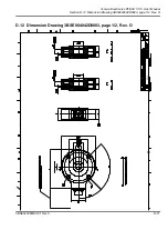
Page 141: ...Tension Electronics PFEA111 112 User Manual Section D 12 Dimension Drawing 3BSE004042D0003 page 1 2 Rev O 3BSE029380R0101 Rev C D 17 D 12 Dimension Drawing 3BSE004042D0003 page 1 2 Rev O ...

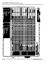
Page 142: ...Tension Electronics PFEA111 112 User Manual Appendix D PFRL 101 Designing the Load Cell Installation D 18 3BSE029380R0101 Rev C D 13 Dimension Drawing 3BSE004042D0003 page 2 2 Rev O ...

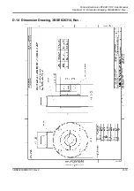
Page 143: ...Tension Electronics PFEA111 112 User Manual Section D 14 Dimension Drawing 3BSE026314 Rev 3BSE029380R0101 Rev C D 19 D 14 Dimension Drawing 3BSE026314 Rev ...

Page 144: ...Tension Electronics PFEA111 112 User Manual Appendix D PFRL 101 Designing the Load Cell Installation D 20 3BSE029380R0101 Rev C D 15 Dimension Drawing 3BSE027249 Rev ...

Page 145: ...Tension Electronics PFEA111 112 User Manual Section D 16 Dimension Drawing 3BSE004042D0066 Rev 3BSE029380R0101 Rev C D 21 D 16 Dimension Drawing 3BSE004042D0066 Rev ...

Page 146: ...Tension Electronics PFEA111 112 User Manual Appendix D PFRL 101 Designing the Load Cell Installation D 22 3BSE029380R0101 Rev C D 17 Dimension Drawing 3BSE004042D0065 Rev ...

Page 147: ...5OC SDCáá CHLDMRHNMR 4 2 ENQL SáBG MFDCáSNá3NKHC7NQJR á SDQH KáMTLADQáNEá á á 3á MCá33áCDKDSDC 0 0 QS áMN N CáBDKKáSXOD á 3 2 0 2 0 2 3 2 0 2 3 2 0 2 C p without express authority is strictly forbidden ABB AB PAMP PAMP PAMP 3BSE010457 Dimension drawing Bracket for PFRL101 Vinkelkonsol för PFRL101 en B 1 1 Hongmei Gao 2014 02 04 Håkan F Wintzell ABB AB 661230 Bansp mätare PRT100 Product family Resp...

Page 148: ...Tension Electronics PFEA111 112 User Manual Appendix D PFRL 101 Designing the Load Cell Installation D 24 3BSE029380R0101 Rev C ...

Page 149: ...ions Each application has its own individual demands that have to be considered though a few basic considerations tend to repeat themselves What type of process is involved papermaking converting etc Is the environment demanding temperature chemicals etc What is the tension measurement purpose indication or closed loop control Are there any specific accuracy demands involved What is the machine de...

Page 150: ...minal load c If the span between maximum and minimum tension in the process is large select load cell so that the maximum tension will be in the load cell extended range when applicable d The measured force component of web tension is recommended to be at least 30 of tare force component roll weight acting in load cell measurement direction The reason for this recommendation is load cell signal st...

Page 151: ...ate and the foundation Web a PFTL 101A AE AER 230 mm 9 in PFTL 101B BE BER 360 mm 14 in a a For correct tightening torques see table E 1 1 0 mm 0 04 in In level Adapter plate thickness PFTL 101A PFTL 101B min 35 mm 1 38 in min 30 mm 1 18 in 90 mm inches Dynamically balanced Self aligning bearings Grade G 2 5 ISO 1940 1 that fulfills at least measuring roll use SKF CARB bearings sliding spherical r...

Page 152: ...culating Force and Calculating Wrap Gain E 5 1 Horizontal Mounting In most cases horizontal mounting is the most obvious and simplest solution The load cell should thus be mounted horizontally when possible FR T cos cos FRtot FR FRT T cos cos FRT 0 Tare force is not measured Wrap gain T F R T T cos cos Wrap gain 1 cos cos T Tension Wrap gain F R FR T Tare ...

Page 153: ...orce component applied to the load cell Inclined mounting adds a component of tare force in the measuring direction and modifies the force components as shown NOTE When calculating it is important that the angles are set into the equations with the correct signs in relation to the horizontal plane FR T cos cos FRtot FR FRT FRT Tare sin T cos cos Tare sin Wrap gain T F R T T cos cos T Tension Wrap ...

Page 154: ...vious and simple solution is horizontal mounting with the web evenly distributed and centered on the roll As long as the roll is supported at both ends the same calculations given in Section E 5 Mounting Alternatives Calculating Force and Calculating Wrap Gain are valid NOTE The accuracy of a single load cell measurement is highly dependent on how well the center of force can be determined Since t...

Page 155: ...ell centerline see figure Calculation procedure 1 Horizontal or inclined mounting 2 Calculate FR and FRT see Section E 5 Mounting Alternatives Calculating Force and Calculating Wrap Gain 3 Use the following equations FR for single load cell FRT for single load cell FRtot for single load cell FR for single load cell FRT for single load cell where L Distance between load cell centerline and the oppo...

Page 156: ...on is done not careful enough especially if the roll is heavy The most critical load cells are naturally the PFTL 101A 0 5 kN and PFTL 101B 2 kN Applications with inclined mounting are most critical 6 Adjust the load cells so that they are in parallel with each other and in line with the axial direction of the roll Tighten the foundation screws see Table E 1 7 Adjust the roll so that it is at righ...

Page 157: ...3 Drilling Dowel Pin Holes E 7 1 Routing the Load Cell Cable The cable must be supported with clamps and routed to prevent force shunting through the cable c c b b NOTE Do not drill in this a B BE BER Tubular dowel pin a a a Load cell PFTL 101 a b c A AE AER 8 15 15 15 12 20 8 4 12 5 area as internal wiring may be damaged ...

Page 158: ...0 B BE BER 30 6740 30 6740 30 6740 40 9000 Permitted axial load within the accuracy FAnom A AE AER 2 450 5 1120 5 1120 B BE BER 5 1120 10 2250 10 2250 10 2250 Overload capacity Max load in measuring direction without permanent change of data Fmax A AE AER 2 5 562 5 1120 10 2250 B BE BER 10 2250 25 5620 50 11200 80 18000 Spring constant A AE AER 32 183 65 372 130 744 kN mm 1000 lbs in B BE BER 130 ...

Page 159: ...y class A AE AER B BE BER 0 5 Linearity deviation 0 3 Repeatability error 0 05 Hysteresis 0 2 Compensated temperature range 20 80 68 176 C F Zero point drift 30 80 1 17 44 1 ppm K ppm F Sensitivity drift 150 83 Working temperature range 10 105 14 221 C F Zero point drift 50 100 1 28 56 1 ppm K ppm F Sensitivity drift 250 139 Storage temperature range 40 105 40 105 C F Degree of protection A B AE B...

Page 160: ...Tension Electronics PFEA111 112 User Manual Appendix E PFTL 101 Designing the Load Cell Installation E 12 3BSE029380R0101 Rev C E 9 Cable Diagram 3BSE028140D0065 Page 3 5 Rev C ...

Page 161: ...Tension Electronics PFEA111 112 User Manual Section E 10 Cable Diagram 3BSE028140D0065 Page 4 5 Rev C 3BSE029380R0101 Rev C E 13 E 10 Cable Diagram 3BSE028140D0065 Page 4 5 Rev C ...

Page 162: ...Tension Electronics PFEA111 112 User Manual Appendix E PFTL 101 Designing the Load Cell Installation E 14 3BSE029380R0101 Rev C E 11 Cable Diagram 3BSE028140D0065 Page 5 5 Rev C ...

Page 163: ...Tension Electronics PFEA111 112 User Manual Section E 12 Dimension Drawing 3BSE004171 Rev B 3BSE029380R0101 Rev C E 15 E 12 Dimension Drawing 3BSE004171 Rev B ...

Page 164: ...Tension Electronics PFEA111 112 User Manual Appendix E PFTL 101 Designing the Load Cell Installation E 16 3BSE029380R0101 Rev C E 13 Dimension Drawing 3BSE004995 Rev C ...

Page 165: ...Tension Electronics PFEA111 112 User Manual Section E 14 Dimension Drawing 3BSE023301D0064 Rev B 3BSE029380R0101 Rev C E 17 E 14 Dimension Drawing 3BSE023301D0064 Rev B ...

Page 166: ...Tension Electronics PFEA111 112 User Manual Appendix E PFTL 101 Designing the Load Cell Installation E 18 3BSE029380R0101 Rev C E 15 Dimension Drawing 3BSE004196 Rev C ...

Page 167: ...Tension Electronics PFEA111 112 User Manual Section E 16 Dimension Drawing 3BSE004999 Rev C 3BSE029380R0101 Rev C E 19 E 16 Dimension Drawing 3BSE004999 Rev C ...

Page 168: ...Tension Electronics PFEA111 112 User Manual Appendix E PFTL 101 Designing the Load Cell Installation E 20 3BSE029380R0101 Rev C E 17 Dimension Drawing 3BSE023223D0064 Rev B ...

Page 169: ...Tension Electronics PFEA111 112 User Manual Section E 18 Dimension Drawing 3BSE012173 Rev F 3BSE029380R0101 Rev C E 21 E 18 Dimension Drawing 3BSE012173 Rev F ...

Page 170: ...Tension Electronics PFEA111 112 User Manual Appendix E PFTL 101 Designing the Load Cell Installation E 22 3BSE029380R0101 Rev C E 19 Dimension Drawing 3BSE012172 Rev F ...

Page 171: ...Tension Electronics PFEA111 112 User Manual Section E 20 Dimension Drawing 3BSE012171 Rev F 3BSE029380R0101 Rev C E 23 E 20 Dimension Drawing 3BSE012171 Rev F ...

Page 172: ...Tension Electronics PFEA111 112 User Manual Appendix E PFTL 101 Designing the Load Cell Installation E 24 3BSE029380R0101 Rev C E 21 Dimension Drawing 3BSE012170 Rev F ...

Page 173: ... application has its own individual demands that have to be considered though a few basic considerations tend to repeat themselves What type of process is involved papermaking converting etc Is the environment demanding temperature chemicals etc What is the tension measurement purpose indication or closed loop control Are there any specific accuracy demands involved What is the machine design like...

Page 174: ...load c If the span between maximum and minimum tension in the process is large select load cell so that the maximum tension will be in the load cell extended range when applicable d The measured force component of web tension is recommended to be at least 30 of tare force component roll weight acting in load cell measurement direction The reason for this recommendation is load cell signal stabilit...

Page 175: ...e load cell immediately above or below Shims must not be placed plate and the foundation Web For correct tightening torques see Table F 1 and Table F 2 1 0 mm 0 04 in In level 90 mm inches Dynamically balanced Self aligning bearings Grade G 2 5 ISO 1940 1 that fulfills at least measuring roll use SKF CARB bearings sliding spherical roller or as a second choice To allow axial expansion the shaft be...

Page 176: ...rtical measurement There are two sources of vertical forces the forces from the web tension and the tare weight of the roll Divide the total vertical force FRtot by two to get the required capacity of each load cell Do not oversize an ABB load cell for overload purposes as the load cell has sufficient overload capacity The load cell can measure tension as well as compression If the T sin sin is la...

Page 177: ...n an incline due to mechanical design constraints of the machine or the need to have a proper force component applied to the load cell In this case the incline angle modifies the tare load and the force components as shown FR T sin sin FRtot FR FRT FRT Tare cos Tare FRT FR T T T sin sin Tare cos PFCL 201 Wrap gain T F R T T sin sin T Tension Wrap gain F R Wrap gain 1 sin sin ...

Page 178: ...st obvious and simple solution is horizontal mounting with the web evenly distributed and centered on the roll As long as the roll is supported at both ends the same calculations given in Section F 5 are valid NOTE The accuracy of a single load cell measurement is highly dependent on how well the center of force can be determined Since the cross directional stress distribution generally is somewha...

Page 179: ...the tension force center and the load cell centerline Calculation procedure 1 Horizontal or inclined mounting 2 Calculate FR and FRT see Section F 5 3 Use the following equations FR for single load cell FRT for single load cell FRtot for single load cell FR for single load cell FRT for single load cell where L Distance between load cell centerline and the opposite bearing centerline a Distance bet...

Page 180: ...gement Variations may be allowed provided that the requirements of Section F 4 are complied with 1 Clean the foundation and other mounting surfaces 2 Fit the lower adapter plate to the load cell Tighten the screws to the torque stated in Table F 1 or Table F 2 and lock them with locking fluid 3 Fit the load cell and the lower adapter plate to the foundation but do not fully tighten the screws 4 Fi...

Page 181: ...Nm Table F 2 Waxed Screws of Stainless Steel According to ISO 3506 Strength class Dimension Tightening torque A2 80 1 1 Strength class 12 9 is recommended for 50 kN load cells when large overloads are expected especially if the fixing screws are subjected to tension M16 187 Nm Pressductor System Rulle Övre mellanläggsplatta Lastcell Undre mellanläggsplatta Lagerhus Fundament Upper adapter plate Lo...

Page 182: ...l differ from the actual The direction of the cable and protecting hose can be changed by unscrewing the connection box and turning it 90 180 Make sure that the cable between the connection box and the load cell does not get jammed or damaged when the connection box is remounted Figure F 4 Allowed Laying of Cable with Protective Hose for PFCL 201CE NOTE The cable with the protective hose must not ...

Page 183: ...1 25 281 2 5 562 5 1120 12 5 2810 Extended load in measuring direction with accuracy class 1 Fext 7 5 1690 15 3370 30 6740 75 16900 Max permitted load In the direction of measurement without permanent change of data Fmax 2 C CD CE 50 11200 100 22500 200 45000 500 3 112000 kN lbs In the transverse direction without permanent change of data FVmax 2 for h 300 mm 12 5 2810 25 5620 50 11200 125 28100 S...

Page 184: ... 50 28 ppm K ppm F Sensitivity drift 100 56 Working temperature range 10 90 14 194 C F Zero point drift 100 56 ppm K ppm F Sensitivity drift 200 111 Storage temperature range 40 90 40 194 C F Table F 3 Technical Data Type PFCL 201 Unit Pressductor System h h 1 Definitions of direction designations V and A in FV and FA are given in Section A 2 1 2 Fmax and FVmax are allowed at the same time 3 Max p...

Page 185: ...Tension Electronics PFEA111 112 User Manual Section F 9 Cable Diagram 3BSE028140D0065 Page 3 5 Rev C 3BSE029380R0101 Rev C F 13 F 9 Cable Diagram 3BSE028140D0065 Page 3 5 Rev C ...

Page 186: ...Tension Electronics PFEA111 112 User Manual Appendix F PFCL 201 Designing the Load Cell Installation F 14 3BSE029380R0101 Rev C F 10 Cable Diagram 3BSE028140D0065 Page 4 5 Rev C ...

Page 187: ...ed Hidden edges removed Geometric tolerances added Dimensions adjusted 2011 12 27 PA FM GF ML C ABB AB without express authority is strictly forbidden 2012 01 13 Cont sh No of sh Sheet Lang Rev Project or order number Modify date Document number Appr Prep Resp dept Product type designation Product information Product family 2012 01 04 14 13 56 PFC100 661130 Bansp mätare VPBT HPBT ABB AB Håkan F Wi...

Page 188: ...Sheet Lang Rev Project or order number Modify date Document number Appr Prep Resp dept Product type designation Product information Product family 2012 01 04 14 09 00 PFC200 661130 Bansp mätare VPBT HPBT ABB AB Håkan F Wintzell 2012 01 11 Magnus X Lindström 1 1 B en Lastcell PFCL 201CD Load cell PFCL 201CD Dimension drawing 3BSE029522D0001 PA PA PA PA FM GF FM GF FM GF Document status Approved Cus...

Page 189: ...t Martensitic stainless Steel Hardness 300 400 HB Yield stress 400MPa N mm CTE 11 13 μm m C Remanent magnetism of finished detail must be less than 2 Gauss 0 0 2mT X12CrMoS13 AT X20Cr13 A W nr 1 4005 AT 1 4021 A ASTM 416 420 or equivalent C duction use or disclosure to third parties without express authority is strictly forbidden ABB AB We reserve all rights in this document and in the information...

Page 190: ...m was 10m 2007 08 21 PA FM GF BS G View A added Views in sheet 2 were in sheet 1 Holes Ø8 0 added Hole callout M16 adjusted Hidden edges removed Geometric tolerances added Dimensions adjusted 2011 12 29 PA FM GF ML H New connection box design 2014 05 06 PAMP FMGE TP I Administrative adjustment 2014 09 29 PAMP FMGE TP J Adapter added 2015 12 17 PAMP OE SF C ABB AB 2015 12 17 Cont sh No of sh Sheet ...

Page 191: ...mT 34CrNiMo6 QT900 Toolox 33 Toolox 44 S690 QT W nr 1 6582 QT900 ASTM 4340 or equivalent Martensitic stainless Steel Hardness 300 400 HB Yield stress 400MPa N mm CTE 11 13 μm m C Remanent magnetism of finished detail must be less than 2 Gauss 0 0 2mT X12CrMoS13 AT X20Cr13 A W nr 1 4005 AT 1 4021 A ASTM 416 420 or equivalent C duction use or disclosure to third parties without express authority is ...

Page 192: ...Tension Electronics PFEA111 112 User Manual Appendix F PFCL 201 Designing the Load Cell Installation F 20 3BSE029380R0101 Rev C ...

Page 193: ... application has its own individual demands that have to be considered though a few basic considerations tend to repeat themselves What type of process is involved papermaking converting etc Is the environment demanding temperature chemicals etc What is the tension measurement purpose indication or closed loop control Are there any specific accuracy demands involved What is the machine design like...

Page 194: ...load c If the span between maximum and minimum tension in the process is large select load cell so that the maximum tension will be in the load cell extended range when applicable d The measured force component of web tension is recommended to be at least 30 of tare force component roll weight acting in load cell measurement direction The reason for this recommendation is load cell signal stabilit...

Page 195: ...ve or below Shims must not be placed plate and the foundation Web For correct tightening torques see Table G 1 and Table G 2 max 1 0 mm 0 04 in In level 90 mm inches PFTL 201C CE a a PFTL 201D DE max 1 5 mm 0 06 in Dynamically balanced Self aligning bearings Grade G 2 5 ISO 1940 1 that fulfills at least measuring roll use SKF CARB bearings sliding spherical roller or as a second choice To allow ax...

Page 196: ...culating Force and Calculating Wrap Gain G 5 1 Horizontal Mounting In most cases horizontal mounting is the most obvious and simplest solution The load cell should thus be mounted horizontally when possible FR T cos cos FRtot FR FRT T cos cos FRT 0 Tare force is not measured Wrap gain T F R T T cos cos Wrap gain 1 cos cos T Tension Wrap gain F R FR T Tare ...

Page 197: ...orce component applied to the load cell Inclined mounting adds a component of tare force in the measuring direction and modifies the force components as shown NOTE When calculating it is important that the angles are set into the equations with the correct signs in relation to the horizontal plane FR T cos cos FRtot FR FRT FRT Tare sin T cos cos Tare sin Wrap gain T F R T T cos cos T Tension Wrap ...

Page 198: ...st obvious and simple solution is horizontal mounting with the web evenly distributed and centered on the roll As long as the roll is supported at both ends the same calculations given in Section G 5 are valid NOTE The accuracy of a single load cell measurement is highly dependent on how well the center of force can be determined Since the cross directional stress distribution generally is somewha...

Page 199: ...nsion force center and the load cell centerline see figure Calculation procedure 1 Horizontal or inclined mounting 2 Calculate FR and FRT see Section G 5 3 Use the following equations FR for single load cell FRT for single load cell FRtot for single load cell FR for single load cell FRT for single load cell where L Distance between load cell centerline and the opposite bearing centerline a Distanc...

Page 200: ...e drawing in Section G 15 and Section G 16 G 7 3 Mounting The instructions below apply to a typical mounting arrangement Variations are allowed provided that the requirements of Section G 4 are complied with 1 Clean the foundation and other mounting surfaces 2 Fit the lower adapter plate to the load cell Tighten the screws to the torque stated in Table G 1 or Table G 2 and lock them with locking f...

Page 201: ...S2 lubricated galvanized screws according to ISO 898 1 Strength class Dimension Tightening torque 8 8 12 9 M24 572 963 Nm 8 8 12 9 M36 1960 3310 Nm Table G 2 Waxed screws of stainless steel according to ISO 3506 Strength class Dimension Tightening torque A2 80 M24 629 Nm A2 80 M36 2160 Nm Pressductor System Upper adapter plate with stop blocks Lower adapter plate with stop blocks Roll Bearing hous...

Page 202: ...tive hose shall be mounted for load cells PFTL 201CE and PFTL 201DE The direction of the cable and protecting hose can be changed NOTE The cable with protective hose shall not be rotated more than 180 from its initial mounting direction otherwise the cable can be damaged Figure G 4 Allowed laying of cable with protective hose for PFTL 201CE and PFTL 201DE Cable with protective hose ...

Page 203: ...uracy FVnom C CE 100 22500 200 45000 250 56200 kN lbs D DE 500 112000 500 112000 Permitted axial load within the accuracy FAnom h 300 mm C CE 20 4500 20 4500 50 11250 kN lbs D DE 100 22500 100 22500 Extended load in measuring direc tion with accuracy class 1 Fext C CE 15 3370 30 6740 75 16900 kN lbs D DE 75 16900 150 33700 Overload capacity Maximal load in measuring direction without permanent cha...

Page 204: ... 9 150 5 9 Weight C CE 35 77 35 77 35 77 kg lbs D DE 80 176 80 176 Material C D CE DE Stainless steel SIS 2387 DIN X4CrNiMo165 Accuracy Accuracy class C D CE DE 0 5 Linearity deviation 0 3 Repeatability error 0 05 Hysteresis 0 2 Compensated temperature range 20 80 68 176 C F Zero point drift 50 28 ppm K ppm F Sensitivity drift 100 56 Working temperature range 10 90 14 194 C F Zero point drift 100 ...

Page 205: ...Tension Electronics PFEA111 112 User Manual Section G 9 Cable Diagram 3BSE028140D0065 Page 3 5 Rev C 3BSE029380R0101 Rev C G 13 G 9 Cable Diagram 3BSE028140D0065 Page 3 5 Rev C ...

Page 206: ...Tension Electronics PFEA111 112 User Manual Appendix G PFTL 201 Designing the Load Cell Installation G 14 3BSE029380R0101 Rev C G 10 Cable Diagram 3BSE028140D0065 Page 4 5 Rev C ...

Page 207: ...re to third parties without express authority is strictly forbidden ABB AB We reserve all rights in this document and in the information contained therein Repro PA PA PA 3BSE008723 Dimension drawing Load Cell PFTL201 C Lastcell PFTL201 C en D 1 1 Lars Erik Nilsson 2011 12 14 Håkan F Wintzell ABB AB 661130 B ät VPBT HPBT P d t f il Resp dept Prep Appr Document number P j t d b Rev Lang Sheet No of ...

Page 208: ...tly forbidden ABB AB We reserve all rights in this document and in the information contained therein Repro PA PA PA 3BSE008904 Dimension drawing Load Cell PFTL201 D Lastcell PFTL201 D en D 1 1 Lars Erik Nilsson 2011 12 14 Håkan F Wintzell ABB AB 661130 Bansp mätare VPBT HPBT 2011 12 14 12 52 43 Product family Product information Product type designation Resp dept Prep Appr Document number Modify d...

Page 209: ...ding to SS ISO2768 m REV DESCRIPTION DATE DEPT INIT E Redrawn and uppdated in Solid Works Previous revision table remowed exist on revision D 2012 01 25 PA FM GF LEN F Adapter for hose added Ø19 was 25 and radius 85 was 150 2017 01 09 IAMA OE SF C duction use or disclosure to third parties without express authority is strictly forbidden ABB AB We reserve all rights in this document and in the info...

Page 210: ...ESCRIPTION DATE DEPT INIT F Redrawn and uppdated in Solid Works Previous revision table remowed exist on revision E 2012 01 24 PA FM GF LEN G Adapter for hose added Ø19 was Ø25 and radius 85 was 150 2017 01 12 IAMA OE SF C duction use or disclosure to third parties without express authority is strictly forbidden ABB AB We reserve all rights in this document and in the information contained therein...

Page 211: ... equivalent Martensitic stainless Steel Hardness 300 400 HB Yield stress 400MPa N mm CTE 11 13 μm m C Remanent magnetism of finished detail must be less than 2 Gauss 0 0 2mT X12CrMoS13 AT X20Cr13 A W nr 1 4005 AT 1 4021 A ASTM 416 420 or equivalent C duction use or disclosure to third parties without express authority is strictly forbidden ABB AB We reserve all rights in this document and in the i...

Page 212: ...olox 33 Toolox 44 S690 QT W nr 1 6582 QT900 ASTM 4340 or equivalent Martensitic stainless Steel Hardness 300 400 HB Yield stress 400MPa N mm CTE 11 13 μm m C Remanent magnetism of finished detail must be less than 2 Gauss 0 0 2mT X12CrMoS13 AT X20Cr13 A W nr 1 4005 AT 1 4021 A ASTM 416 420 or equivalent C duction use or disclosure to third parties without express authority is strictly forbidden AB...

Page 213: ... N m kN m kg m pli Web width m inch Object type Load cells per roll Standard roll 2 load cells Standard roll 2 load cells Single side A B 1 load cell Single side A B 1 load cell Load cell nominal load kN lbs Set wrap gain Wrap gain Voltage output Filter settings ms High Tension N kN kg lbs N m kN m kg m pli High Output V Low Tension N kN kg lbs N m kN m kg m pli Low Output V High Limit V Low Limit...

Page 214: ...SE029380R0101 Rev C If HangWeight has been used at commissioning go to menu EnterWrapGain read the Wrap gain value calculated by the electronics and fill in this Wrap gain value in the table Low Limit mA PROFIBUS Address Measuring Range N kN kg lbs N m kN m kg m pli Data and Settings PFEA111 PFEA112 Unit ...

Page 215: ......

Page 216: ...3BSE029380R0101 en Rev C ABB AB Industrial Automation Force Measurement SE 721 59 Västerås Sweden Tel 46 21 32 50 00 Internet www abb com webtension Measurement Analytics ...

Reviews: