1
2TLC172007M0203_B.doc
Startup guide for Pluto Safety PLC, connected in a bus system
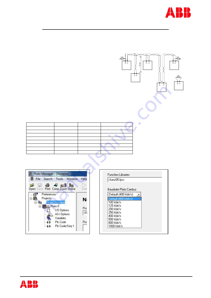
1. Check the bus cable
·
How many meters of bus cable have been
used?
·
Is the system connected with stub
cables?
·
How long is each stub?
·
What is the total length of stub cables?
·
Resistors for end termination must only
be connected in the beginning and the
end of the system.
·
When measuring the resistance between
CH and CL at one Pluto (all units shall be
dead) the resistance shall be somewhat
under 60
Ω
.
The following data are necessary to select the correct communication speed in the system. A lower speed
gives the possibility to communicate over a longer distance, but it results in that somewhat fewer Pluto’s can
be connected. A more detailed description can be found in the Pluto Hardware Manual, chapter Bus
communication.
Bus speed
Cable length
Stub length
Total stub length
100 kbit/s
600 m
25 m
120 m
125 kbit/s
500 m
20 m
100 m
200 kbit/s
300 m
13 m
70 m
250 kbit/s
250 m
10 m
50 m
400 kbit/s
150 m
6 m
30 m
500 kbit/s
100 m
5 m
25 m
800 kbit/s
60 m
3 m
15 m
1 Mbit/s
< 20 m
1 m
5 m
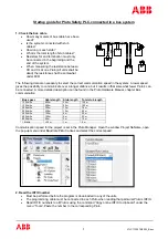
Communication speed for the project is set in the Pluto Manager. Open the window Project NoName, open
the pop-up menu under Baudrate Pluto Canbus and select the correct speed.
2. Read the IDFIX number
·
Must be performed before the program is downloaded to any of the units.
·
The programming cable must be connected to each Pluto when reading that particular Pluto’s IDFIX.
·
Read IDFIX numbers to all Pluto’s using the command “Copy online IDFIX to clipboard” under the
menu “Tools”. Paste the number to the corresponding Pluto.


