background image

ABB Automation Inc.
Substation Automation and Protection Division
Coral Springs, FL 33065

Instruction Leaflet

All possible contingencies which may arise during installation, operation or maintenance, and all details and
variations of this equipment do not purport to be covered by these instructions. If further information is desired
by purchaser regarding this particular installation, operation or maintenance of this equipment, the local ABB
Power T&D Company Inc. representative should be contacted.

Printed in U.S.A

.

41-973.5R

Type PM Line of Relays 
For Pilot-Wire Monitoring 
and Transferred Tripping

Effective: November 1999
Supersedes I.L. 41-973.5Q Dated February 1996

( ) Denotes change since previous issue

!

CAUTION

Before putting protective relays into service,
remove all blocking which may have been
inserted for the purpose of securing parts during
shipment, make sure that all moving parts oper-
ate freely, inspect the contacts to see that they
are clean and close properly, and operate the
relay to check the settings and electrical connec-
tions.

1.0 APPLICATION

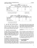
Type PM Monitoring Relays provide continuous moni-
toring of a pilot-wire circuit to detect open circuits,
short circuits, grounds, and wire reversal. In addition,
transferred tripping can be effected where the PM-3,
PM-13, PMG-13 or PM-23 relays are used. Table 1
illustrates the functions available with each relay. A
10 mfd. Capacitor is supplied with each PM relay.
This capacitor provides an ac path between the two
halves of the insulating transformer secondary wind-
ings as shown in figures 25 through 31.

Any relay which has a ground detection unit (5 unit),
may have a momentary contact closure when a
ground occurs on the station battery. If the momen-
tary contact closure causes a problem, relays are
available with an auxiliary telephone relay which has
a pickup delay to eliminate this problem

Each circuit requires the following:

2.0 CONSTRUCTION

PM relays consist of the following:

At one end to introduce monitoring current

One of the following:

For ac supply

For dc Supply

PMA

PMD

PMA-1

PMD-1

PM-13 or PMG-13 (ac)

PM-13 or PMG-13 (dc)

At the other end to receive monitoring current (two termi-
nal line):

One PM-23 or PM-2 or PM-4

At the other ends to receive monitoring current (three 
terminal line):

One PM-23 or one PM-4 or one PM-2 for each remote 
terminal.

PMA

PMA-1

1 Polar Alarm Unit (1)
1 Polar Ground Unit (5)
1 Tapped Transformer
1 Full-Wave Rectifier
3-4 mfd Capacitors
1 set of Potential Divider 
Resistors

1 Polar Alarm Unit
1 Tapped Transformer
1 Full-Wave Rectifier
1-4 mfd Capacitor
1 Set of Potential Divider 
Resistors

PMD

PMD-1

1 Polar Alarm Unit (1)
1 Polar Ground Unit (5)
2-4 mfd Capacitors
1 Set of Potential Divider 

Resistors

1 Polar Alarm Unit
1 Set of Potential Divider 

Resistors

Summary of Contents for PM5 Series

Page 1: ...PM 13 PMG 13 or PM 23 relays are used Table 1 illustrates the functions available with each relay A 10 mfd Capacitor is supplied with each PM relay This capacitor provides an ac path between the two halves of the insulating transformer secondary wind ings as shown in figures 25 through 31 Any relay which has a ground detection unit 5 unit may have a momentary contact closure when a ground occurs o...

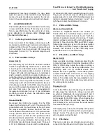
Page 2: ...M 23 PM 2 1 Polar Alarm Unit 2 1 Polar Trip Unit 3 1 Indicating Contactor Switch ICS 1 Milliammeter 5 0 mA 1 Set of Adjustable and Fixed Resistors 2 Blocking Rectifiers 1 Polar Alarm Unit 2 1 Milliammeter 5 0 mA 1 Set of Adjustable Resistors 1 Blocking Rectifier PM 3 PM 4 1 Polar Trip Unit 3 1 Resistor 1 Blocking Rectifier 1 Indicating Contactor Switch ICS 1 Blocking Rectifier 1 Set of Adjustable ...

Page 3: ...et pro vides restraint for the armature and thus controls the pickup value of the switch PMD MDG 13 with Tel Relay In the relays type PMD and PMG 13 where they are energized with dc power supply the ground polar unit 5 could momentarily close its contact for about 10 ms if either positive or negative supply is grounded To eliminate this momentary operation a telephone relay with a nominal operatin...

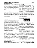
Page 4: ... PMG 13 source relays has its midpoint grounded through a current limiting resistor Thus a pilot wire ground will cause an increase in current in one coil circuit and a decrease in the other one This unbal ance in the current flowing through the two windings 5 of the ground alarm relay unit will cause it to close one of its contacts depending on which point wire is grounded to give an alarm Ground...

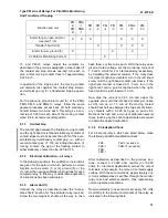
Page 5: ...e tap block to the desired setting by means of a screw connection 4 9 TRIP CIRCUIT CONSTANT Indicating Contactor Switch ICS 5 0 SETTINGS Operating units of all relays are adjusted in the fac tory to the values listed in Tables 4 and 5 to a toler ance of 8 No settings are required on these units For all 48 125 volt dc relays connect jumpers across resistors as shown on the internal schematics 5 1 P...

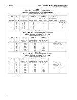
Page 6: ...RS FOR DC REMOTE TRIPPING 2 REQUIRED PER STATION Line Terminals dc Voltage Station A PMG 13 or PM 13 Station B PM 2 PM 3 or PM 23 or PM 4 Station C PM 2 PM 3 or PM 23 or PM 4 To Operate 2 3 48 125 250 48 125 250 200 2120 5600 200 1500 4000 200 2120 5600 200 1500 4000 200 1500 4000 PMG 13 or PM 13 and PM 23 or PM 3 Table 3B PMG 13 AND PM 13 AC SUPPLY APPLICATIONS RESISTORS FOR DC REMOTE TRIPPING 2 ...

Page 7: ...ounting Theterminal studs maybe easily removed or inserted by locking two nuts on the stud andthen turning the proper nut with a wrench For detailed FT case information refer to Instruction Leaflet 41 076 Where the potential to ground impressed on the relays can exceed 700 volts a drainage reactor in conjunction with its surge protectors or the reactor in conjunction with 700 volt carbon block arr...

Page 8: ...ot wire ground test To check the pickup current of the ground detector first remove to the 20 000 ohm resistor from terminals 6 and 7 Connect a 0 1 dc milliammeter in series with a variable resis tor of about 50 000 ohms between terminals 3 and 6 The ground unit should close its left hand contact at approximately 0 3 mA dc With the milliammeter and resistor connected between terminals 3 and 7 the ...

Page 9: ...sistors can readily be seen from the external schematic figure 27 7 1 8 PMG 13 Relays ac and dc Alarm and Tripping Units Follow the procedure given in the previous section for the ac and dc PM 13 relays Ground Unit 5 Connect the 20 000 ohm or 10 000 ohm resistor and milliammeter across terminals 8 and 9 With rated voltage applied and one mA or 2 mA flowing successively short circuit terminals 3 an...

Page 10: ... to close the right hand contact or decreases the amount of current required to close the left hand contact with the proper direction of cur rent flow Also if a relay trips to the right at the proper current the dropout current can be raised by turning in the right hand shunt The two shunt screw adjustments are not independent however and a certain amount of trimming adjustment of both shunt screw...

Page 11: ...netic shunts all the way in then back them out five turns each With the relay ener gized at rated voltage set the monitoring current at 1 3 or 2 3 mA dc for 2 or 3 terminal relay respectively by adjusting the external resistor If the relay does not close its right hand contact turn in the left shunt screw until the right hand contact just closes If the right hand contact is closed at 1 3 mA turn i...

Page 12: ...st be blocked open so as not to affect the tripping unit pickup This will give approximately 2 mA through the relay coil Now draw out the left hand shunt until the relay resets with toggle action not gradually at not less than 10 volts dc When the calibration is approximately cor rect again apply 125 volts dc to the indi cated terminals then recheck the pickup and dropout voltage making any neces ...

Page 13: ... armature will move gradually as the current is changed for this relay unit 9 1 10 ICS Unit Close the main relay tripping contact circuit with a jumper connected directly across the contact termi nals of the polar unit Pass sufficient direct current through the relay trip circuit to close the contacts of the ICS unit This value of current should not be greater than the ICS tap setting being used 0...

Page 14: ...dc supply three terminal line page 23 20 PMG 13 Relay ac supply two or three terminal line page 24 21 PMG 13 Relay dc supply with Telephone Relay Output two terminal line page 24 22 PMG 13 Relay dc supply with Telephone Relay Output three terminal line page 25 23 PMD Relay dc supply with Telephone Relay Output two terminal line page 25 24 PMD Relay dc supply with Telephone Relay Output three termi...

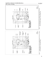
Page 15: ...sferred Tripping Figure 2 Internal Schematic of the Type PMA Relay in FT 31 case 120 volt 60 hertz supply for two terminal lines Figure 3 Internal Schematic of Type PMA 1 Relay in the FT 21 case 120 volts 60 hertz supply for two terminal lines Sub 3 184A500 Sub 3 184A514 ...

Page 16: ...ransferred Tripping Figure 4 Internal Schematic of Type PMA Relay in FT 31 case 120 volt 60 hertz supply for three terminal lines Figure 5 Internal Schematic of Type PMA 1 Relay in FT 21 case 120 volt 60 hertz supply for three terminal lines Sub 1 187A191 Sub 1 187A192 ...

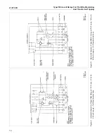
Page 17: ...oring And Transferred Tripping Figure 6 Internal Schematic of the Type PMD Relay in FT 21 case dc supply for two terminal lines Figure 7 Internal Schematic of the Type PMD 1 Relay in the FT 11 case dc supply for two terminal lines Sub 2 184A497 Sub 2 184A498 ...

Page 18: ...g And Transferred Tripping Figure 8 Internal Schematic of the Type PMD Relay in the FT 21 case dc supply for three terminal lines Figure 9 Internal Schematic of the Type PMD 1 Relay in the FT 11 case dc supply for three terminal lines Sub 5 184A583 Sub 4 184A582 ...

Page 19: ...of Relays For Pilot Wire Monitoring And Transferred Tripping Figure 10 Internal Schematic of the Type PM 2 Relay in the FT 21 case Figure 11 Internal Schematic of the Type PM 3 Relay in the FT 11 case Sub 4 184A489 Sub 2 184A484 ...

Page 20: ...12 Internal Schematic of the Type PM 4 Auxiliary Unit in the small molded case Figure 13 Internal Schematic of the Type PM 5 Ground Detector Relay in the FT 11 case Sub 7 2D1845 Sub 2 184A501 POS POS WITH EQUAL CURRENT FLOWING THROUGH BOTH WIRINGS WITH INDICATED POLAR TYPE THERE IS NO NET TORQUE ...

Page 21: ...t Wire Monitoring And Transferred Tripping Figure 14 Internal Schematic of the Type PM 23 Relay in the FT 21 case Figure 15 Internal Schematic of the Type PM 13 Relay in the FT 32 case dc supply for two terminal lines Sub 3 187A874 Sub 5 184A495 ...

Page 22: ...rred Tripping Figure 16 Internal Schematic of the type PM 13 Relay in the FT 32 case dc supply for three terminal lines Figure 17 Internal Schematic of the Type PM 13 Relay in the FT 32 case 120 volt 60 hertz supply for two or three terminal lines Sub 4 184A650 Sub 5 184A512 ...

Page 23: ...And Transferred Tripping Figure 18 Internal Schematic of the Type PMG 13 Relay in the FT 32 case dc supply for two terminal lines Figure 19 Internal Schematic of the type PMG 13 Relay in the FT 32 case dc supply for three terminal lines Sub 3 184A499 Sub 4 184A658 ...

Page 24: ...ripping Figure 20 Internal Schematic of the Type PMG 13 Relay in the FT 32 case 120 volts 60 hertz supply for two or three terminal lines Figure 21 PMG 13 Relay with Ground Alarm and Remote Trip two terminal lines with Telephone Relay Output FT 32 case Sub 4 184A513 Sub 11 3490A59 ...

Page 25: ...nsferred Tripping Figure 22 PMG 13 Relay with Ground Alarm and Remote Trip three terminal lines with Telephone Relay output FT 32 case Figure 23 PMD Relay Ground Alarm D P D T Contacts two terminal lines with Telephone Relay Output FT 21 case Sub 3 3490A60 Sub 3 3490A61 ...

Page 26: ...73 5R 26 Type PM Line of Relays For Pilot Wire Monitoring And Transferred Tripping Figure 24 PMD Relay Ground Alarm D P D T Contacts three terminal lines with Telephone Relay Output FT 21 case Sub 3 3490A62 ...

Page 27: ...41 973 5R 27 Type PM Line of Relays For Pilot Wire Monitoring And Transferred Tripping Figure 25 External Schematic of the type PMD Relay with Type PM 23 or PM 4 Relay two terminal lines Sub 4 719B530 ...

Page 28: ...41 973 5R 28 Type PM Line of Relays For Pilot Wire Monitoring And Transferred Tripping Figure 26 External Schematic of the Type PMA Relay with Type PM 23 or PM 4 Relay two terminal lines Sub 8 290B247 ...

Page 29: ... 973 5R 29 Type PM Line of Relays For Pilot Wire Monitoring And Transferred Tripping Figure 27 External Schematic of the dc Type PMG 13 Relay with Type PM 23 or PM 4 Relay two terminal lines Sub 5 719B528 ...

Page 30: ...1 973 5R 30 Type PM Line of Relays For Pilot Wire Monitoring And Transferred Tripping Figure 28 External Schematic of the Type PMD Relay with Type PM 23 and PM 4 Relays three terminal lines Sub 4 719B529 ...

Page 31: ...41 973 5R 31 Type PM Line of Relays For Pilot Wire Monitoring And Transferred Tripping Figure 29 External Schematic of the ac Type PMG 13 with Type PM 23 Relay two terminal lines Sub 7 290B250 ...

Page 32: ... 5R 32 Type PM Line of Relays For Pilot Wire Monitoring And Transferred Tripping Figure 30 External Schematic of the dc Type PM 13 and PM 5 Relay with Type PM 23 or PM 4 Relay two terminal lines Sub 6 290B253 ...

Page 33: ... 973 5R 33 Type PM Line of Relays For Pilot Wire Monitoring And Transferred Tripping Figure 31 External Schematic of the dc Type PM 13 Relay with Type PM 23 or PM 4 Relay two terminal lines Sub 6 290B258 ...

Page 34: ...s For Pilot Wire Monitoring And Transferred Tripping Figure 32 Outline and Drilling Plan for 10 mfd capacitor for references only Figure 33 Outline and Drilling Plan for External Remote Trip Resistor Assembly Sub 5 184A657 Sub 2 183A413 ...

Page 35: ...toring And Transferred Tripping Sub 1 184A989 Figure 34 Outline and Drilling Plan for the Type PM 4 auxiliary Unit in the projection molded case Figure 35 Outline and Drilling Plan for the Type PM 4 Auxiliary Unit in the Semi Flush molded case Sub 4 26D588 ...

Page 36: ...41 973 5R 36 Type PM Line of Relays For Pilot Wire Monitoring And Transferred Tripping Figure 36 Outline and Drilling Plan for the Type PM 3 PM 5 PMD 1 Relays in the Type FT 11 case 57D7900 Sub 20 ...

Page 37: ... 973 5R 37 Type PM Line of Relays For Pilot Wire Monitoring And Transferred Tripping Figure 37 Outline and Drilling Plan for the Type PM 2 PM 23 PMA 1 and PMD Relays in the Type FT 21 case Sub 17 57D7901 ...

Page 38: ...41 973 5R 38 Type PM Line of Relays For Pilot Wire Monitoring And Transferred Tripping Figure 38 Outline and Drilling Plan for the Type PMA Relay in the Type FT 31 case Sub 17 57D7902 ...

Page 39: ...41 973 5R 39 Type PM Line of Relays For Pilot Wire Monitoring And Transferred Tripping Figure 39 Outline and Drilling Plan for the Type PM 13 and PMG 13 Relays in the Type FT 32 case Sub 17 57D7903 ...

Page 40: ...BB Automation Inc 4300 Coral Ridge Drive Coral Springs Florida 33065 TEL 954 752 6700 FAX 954 345 5329 visit our website at www abbus com papd Printed in U S A ABB Automation Inc 4300 Coral Ridge Drive Coral Springs Florida 33065 TEL 954 752 6700 FAX 954 345 5329 visit our website at www abbus com papd ...

Reviews: