41-973.5R
3
Type PM Line of Relays For Pilot Wire Monitoring
And Transferred Tripping
2.1
POLAR UNIT
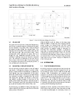
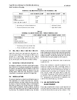
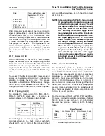
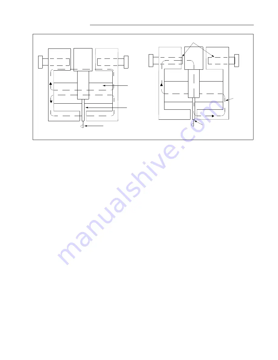
The polar unit consists of a rectangular shaped mag-
netic frame, an electromagnet, a permanent magnet,
and an armature. The poles of the crescent shaped
permanent magnet bridge the magnet frame. The
magnetic frame consists of three pieces joined in the
rear with two brass rods and silver solder. These
nonmagnetic joints represent air gaps, which are
bridged by two adjustable magnetic shunts. The
winding or windings are wound around a magnetic
core. The armature is fastened to this core and is
free to move in the front air gap. The moving contact
is connected to the free end of a leaf spring, which, in
turn, is fastened to the armature.
2.2
INDICATING CONTACTOR SWITCH
The dc indicating contactor switch is a small clapper
type device. A magnetic armature, to which a leaf-
spring mounted contacts are attached, is attracted to
the magnetic core upon energization of the switch.
When the switch closes, the moving contacts bridge
two stationary contacts, completing the trip circuit.
Also during this operation two fingers on the arma-
ture deflect a spring located on the front of the
switch, which allows the operation indicator target to
drop. The target is reset from the outside of the case
by a push rod located at the bottom of the cover.
The front spring, in addition to holding the target, pro-
vides restraint for the armature and thus controls the
pickup value of the switch.
PMD & MDG-13 with Tel. Relay: In the relays type
PMD and PMG-13 where they are energized with dc
power supply, the ground polar unit (#5) could
momentarily close its contact (for about 10 ms) if
either positive or negative supply is grounded. To
eliminate this momentary operation, a telephone
relay with a nominal operating time of 25 ms was
connected in series with contact of the “5” unit, and
the contact of the telephone relay is used as an over-
all contact of the “5” unit. This type of relay should be
used where the dc power supply is subjected to
short-to-the-ground.
3.0 OPERATION
3.1
PILOT WIRE MONITORING
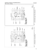
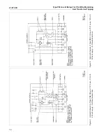
Monitoring current is introduced into the pilot-wire as
sown in the external schematics, figures 25 to 31, by
the monitoring current source. External schematics
showing other combinations are available upon
request. A nominal 20 volts is impressed across the
10 mfd capacitor at the left-hand line terminal in fig-
ures 25 to 31. This voltage produces a current circu-
lating through one winding of the HCB insulating
transformer, one pilot-wire, the PM-23, PM-2 or PM-
4, and back through the other pilot-wire and the other
winding of HCB insulating transformer.
Adjustment of the resistors of the PM-23, PM-2 or
PM-4 relay at the other end of the pilot-wire provides
a normal one-milliampere dc circulating current. In
N
N
S
S
N
N
S
S
Moving Contact
Armature
Permanent
Magnet
BALANCED AIR GAPS
UNBALANCED AIR GAPS
N
Additional
Flux Path
Shunt
Figure 1: Polar Unit Permanent Magnet Flux Paths.
Illustration

