background image

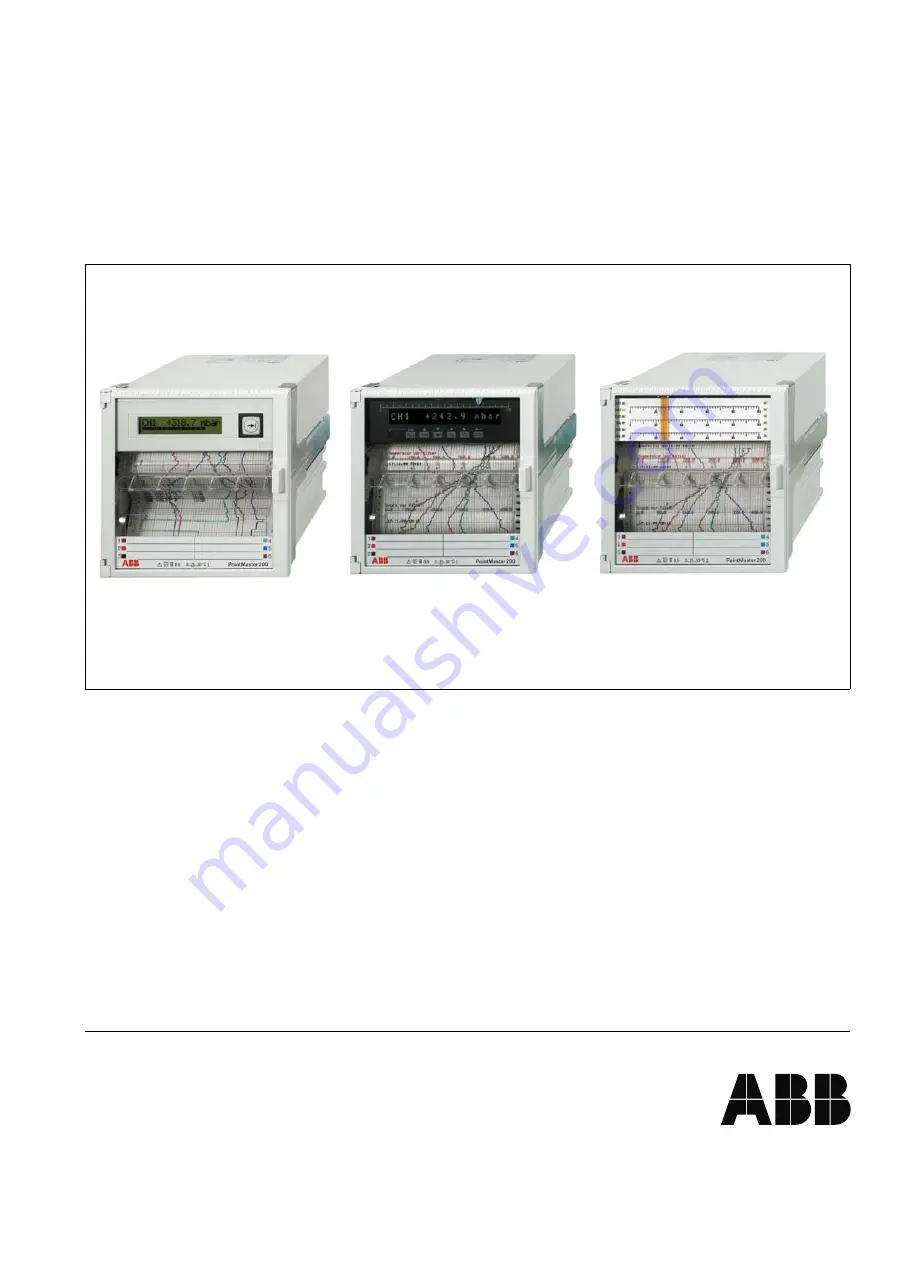
PointMaster 200

6-channel Multipoint Recorder
Version with LC display
Version with LED display
Version with scales

Operating manual - Interface Description

42/41-25 EN

Rev. 0.0

Summary of Contents for PointMaster 200 Series

Page 1: ...PointMaster 200 6 channel Multipoint Recorder Version with LC display Version with LED display Version with scales Operating manual Interface Description 42 41 25 EN Rev 0 0 ...

Page 2: ...s 1AH 18 DI assignment 1BH 19 Date and time 1CH 20 Calibration data 1DH 20 Channel measured values and instrument status 1EH 20 Entering measured values into recorder 1FH 22 Reading accounting data 20H 23 Writing equipment status 21H 24 Creation of text blocks 25 Send printout lines to recorder 25 Scanning of printer status 26 Sending a display line to the recorder F2H 26 Error register for commun...

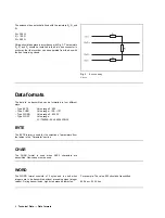
Page 3: ...rs 32 active and passive Transmission speed 600 1200 2400 4800 9600 19200 baud Type of transmission symmetrical Driver output idle state 5 V with load 1 5 V load resistance 60 Ω Receiver sensitivity 200 mV input resistance 12 kΩ Grounding The shield should be grounded on both ends to arrest high frequency fault states Potential balancing Potential variations between the data reference potentials G...

Page 4: ...rent ways Type BYTE Value range 0 255 Type CHAR Value range 128 127 Type WORD Value range 0 65535 Type FLOAT Value range 1 175494E 38 3 402823E 38 BYTE The BYTE format is used for the selection of parameters from the tables in the Parameter section CHAR The CHAR format is used when ASCII characters are transmitted Hex codes must be used WORD The WORD format consists of 2 bytes and is used when int...

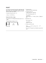
Page 5: ...e binary display of the figure 12 5 is 11000001 01001000 00000000 00000000 Exp Rest 8 bit 23 bit negative sign 1 Calculate the sign the bit is set in case of a negative sign 2 Calculate the exponent the highest exponent is calculated EXP INT lg Figuredec lg2 127 in the example INT lg12 5 lg2 127 130 dec 82 hex 10000010 bi nary 3 Calculate the rest Rest Figuredec 2Exp in the example 12 5 2130 127 1...

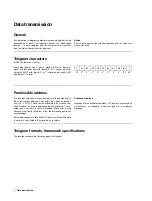
Page 6: ... b6 b7 b8 P 1 ST 20 21 22 23 24 25 26 27 P SP Permissible address The recorder only answers queries which use the address set in the unit as target address Permissible are values between 0 and 126 7E H These can be allocated in any manner de sired However no double addresses may be allocated The re corder does not reply to faulty messages check sum wrong address other faulty reception Also faulty ...

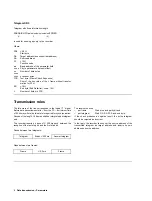
Page 7: ...N xxx Manufacturer s code CT 41422 xxx Catalog number and apparatus HR CPU A Index of the recorder CPU card SR 00 00 16 Example for software release Telegram SD2 Telegram with variable information field length SD2 LE LEr SD2 DA SA FC aa oo oo cc data field FCS ED L is used for sending data to the recorder and for sending replies from the recorder Where SD2 68H Start byte LE Number of data bytes 7 ...

Page 8: ...the logical 1 signal Before data transmission starts from the PC a minimum time of 33 bits syn time as idle state is required for synchronisation Pauses of the length 3 frames shall be interpreted as telegram end The recorder inserts a pause of 300 ms each between the reception of the last stop bit and the first start bit Pause between two telegrams Telegram Break 300 ms Answer telegram Gaps betwe...

Page 9: ... channel 6 Text lines Print intervals Print synchronisation times Print colours DI assignment Date and time Calibration data Measured values and equipment status Sending measured values to the recorder Reading accounting data block transfer Writing the equipment status Sending the print line Sending the display line to the recorder Communication error register 10H 11H 12H 13H 14H 15H 16H 17H 18H 1...

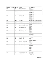
Page 10: ...H Byte Delay for exctrenal control 00H 1EH 0 30 s 0008H Byte Number of event markers 00H without 01H 1 0AH 10 0009H Byte Date time format 00H European 01H American 000AH Byte Type of simulation 00H off 01H Ramp 02H Sinus 03H Step 10 000BH Word Simulation period 0014 07D0H 20 2000 s 000DH Time Time for external clock synchronisation Hour high byte 00 23 00 17H Minute low byte 00 59 00 3BH 000FH Byt...

Page 11: ...g current 0022H Word Password 0000 270EH 0 9998 0024H Word Increment for counter 0000H 03E8 0 1000 0026H Byte Counting direction 00H adding 01H subtracting 0027H Byte Assigned text line 00H Counter off 01H Text line 1 0AH Text line 10 0028H Word Set counter upper 4 digits 0000H 270FH 0 9999 002AH Word Set counter lower 4 digits 0000H 270FH 0 9999 002CH Word Formation of message block 1 The coding ...

Page 12: ...C8H 0 200 min 0036H Word Standby threshold coding 0000H inactive 0001H channel 1 threshold 1 0002H channel 1 threshold 2 0004H channel 2 threshold 1 0008H channel 2 threshold 2 0010H channel 3 threshold 1 0020H channel 3 threshold 2 0040H channel 4 threshold 1 0080H channel 4 threshold 2 0100H channel 5 threshold 1 0200H channel 5 threshold 2 0400H channel 6 threshold 1 0800H channel 6 threshold 2...

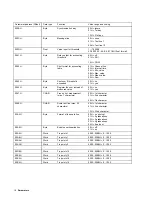
Page 13: ...B 15H TC E 16H TC J 17H TC K 18H TC L 19H TC N 1AH TC R 1BH TC S 1CH TC T 1DH TC U 1EH RS 485 0001H Byte Temperature unit 00H C 01H F 0002H Byte Physical unit of measurement 00H free unit 01H mA 02H A 03H mV 04H V 05H mbar 06H bar 07H Pa 08H kPa 09H C 0AH F 0BH K 0CH l s 0DH l min 0EH 0FH 10H kW 11H MW 12H 1 min 13H m3 h 0003H Byte Display format 00H linear 01H linear with 2 increments 02H linear ...

Page 14: ... Byte Recording range end 10 100 002FH Integer Offset measured value correct 1000 1000 0033H Byte Filter time 00 3CH 0 60 s 0034H Byte Recording direction 00H no 01H yes 0035H Byte Square root extraction 00H off 01H on 0036 Byte Reference junction temperature 00H 0 C 01H 20 C 02H 50 C 03H 60 C 04H 70 C 05H internal 06H Channel 6 0037H Byte Number of decimal places for measured value representation...

Page 15: ...ction threshold 1 00H min 01H max 004FH Byte Effective direction threshold 2 00H min 01H max 0050H Byte Relay output for threshold 1 00H off 01H DO 1 14H DO 20 0051H Byte Relay output for threshold 2 00H off 01H DO 1 14H DO 20 0052H Byte Text line for threshold 1 00H none 01H Text line 1 0AH Text line 10 0053H Byte Text line for threshold 1 as for threshold 1 0056H Byte Accounting Mode 00H off 01H...

Page 16: ...um instead of measured value 00H no 01H yes 0067H CHAR Free unit of measurement max 7 characters 00H 1st character 01H 2nd character 06H 7th character 006EH CHAR Scale text line max 32 characters 00H 1st character 01H 2nd character 1FH 32nd character 00A4H Byte Format of the scale line 00H no printout 01H 2 graduations 02H 3 graduations 03H 5 graduations 04H free input 00A5H Byte Enable user linea...

Page 17: ...ith 20H and a negative acknowledgment is sent as a reply Print intervals 18H Parameter address Offset Data type Function Value range and coding 0000H Byte Print interval for text line 1 00H off 01H 10 min 02H 20 min 03H 1 h 04H 2 h 05H 3 h 06H 4 h 07H 6 h 08H 8 h 09H 12 h 0AH 24 h 0001H Byte Print interval for text line 2 as text line 1 0002H Byte Print interval for text line 3 as text line 1 0003...

Page 18: ... Byte Print colour for measuring channnel 1 00H none 01H violet 02H red 03H black 04H green 05H blue 06H brown 0001H Byte Print colour for measuring channnel 2 as measuring channel 1 0002H Byte Print colour for measuring channnel 3 as measuring channel 1 0003H Byte Print colour for measuring channnel 4 as measuring channel 1 0004H Byte Print colour for measuring channnel 5 as measuring channel 1 0...

Page 19: ...as event marker 1 0006H Byte Trigger printout of text line 3 as event marker 1 0007H Byte Trigger printout of text line 4 as event marker 1 0008H Byte Trigger printout of text line 5 as event marker 1 0009H Byte Trigger printout of text line 6 as event marker 1 000AH Byte Trigger printout of text line 7 as event marker 1 000BH Byte Trigger printout of text line 8 as event marker 1 000CH Byte Trigg...

Page 20: ...000 FFFF 000EH Word Upper range value channel 4 0000 FFFF 0010H Word Lower range value channel 5 0000 FFFF 0012H Word Upper range value channel 5 0000 FFFF 0014H Word Lower range value channel 6 0000 FFFF 0016H Word Upper range value channel 6 0000 FFFF 0018H Word O point offset print head 0 100 001AH Word Total number of increments 980 1000 001CH Word O point offset scale 0 100 Channel measured v...

Page 21: ...en CPU and clock 05 A D converter error 06 Check sum error parameter data CPU card 07 Reading error with EEPROM on CPU card 08 Writing error with EEPROM CPU card 09 Check sum error calibration data channel card 0A Reading error with EEPROM on channel card 0B Writing error with EEPROM channel card 0C Watchdog generates device reset 0D Printer queue full 0E Print head stuck 0F Voltage interruption t...

Page 22: ...l 1 0038H D Word Counter for hours of operation Operating time in minutes hex coded Entering measured values into recorder 1FH Measured values are entered into the recorder using an SD2 type message The parameter field address 1FH is to be used as the basic address The measured values are transmitted in the form of standardised values The permitted range of numbers is 0 1000 The recor der does not...

Page 23: ...re SD3 A2H Start byte DA Destination address bus subscriber address SA Source address FC 15H Function code aa 20H Basic address of the parameter field bb bb 2 bytes parameter address offset cc 27H Number of data bytes xx xx xx xx 4 random bytes FCS Test byte Frame Check Sequence Sum of the hex value of the L frame without transfor mation for FFH ED 16H End byte End Delimiter code 16H L Number of b...

Page 24: ...parameter field address is used for entering the length of the new roll of paper after changing the chart paper It is possible to excite the channel specific line pairs scale line and text line such that they are printed out immediately Parameter address Offset Data type Function Value range and coding 0000H Word Paper length entry in cm 0000H do not change 0001H 0C80H 1 3200 0006H Byte Save param...

Page 25: ...queue has no more free space the acknowledgement code 11H is sent in response The message format is SD2 LE LEr SD2 DA SA FC aa bb cc dd ee ff Textline FCS ED L Where SD2 68H Start byte LE Number of data bytes 7 LEr Repetition of LE SD2 68H Repetition of start byte DA Target address bus subscriber address SA Source address FC 16H Function code aa F1H Basic address of the parameter field bb 00H Fill...

Page 26: ... queue FCS Test byte Frame Check Sequence Sum of the hex value of the L frame without transfor mation for FFH ED 16H End byte End Delimiter code 16H L Number of bytes in FCS Sending a display line to the recorder F2H This message is used to send a text line with max 16 characters to the recorder The message appears on the display if the control byte is set to the value 01H The message format is SD...

Page 27: ...r FFH ED 16H End byte End Delimiter code 16H L Number of Bytes in FCS The answer of the recorder is SD2 LE LEr SD2 DA SA FC aa bb cc dd ee FCS ED Where SD2 68H Start byte LE 17H Number of data bytes 7 LEr Repetition of LE SD2 68H Repetition of start byte DA Target address bus subscriber address B SA Source address FC 15H Function code aa requested data field length bb Type of error 00H no error 01...

Page 28: ...r High Byte Low Byte Modification of 2 values with telegram SD3 and function code 07H The computer query is SD3 DA SA FC c1 a1 val1 c2 a2 val2 FCS ED L Where SD3 A2H Start byte DA Destination address bus subscriber address SA Source address FC 07H Function code c1 01H Triggers modification in device a1 Parameter address from section Parameter addresses val1 Parameter value c2 01H triggers modifica...

Page 29: ...ardised Speed index 1 Speed index 2 Day of recorder internal clock Month Year Hour Minute 10H 11H 12H 13H 14H 15H Thresholds for channel 1 Threshold 1 standardised Threshold 2 standardised Function threshold 1 0 min 1 max Function threshold 1 0 min 1 max Relay output for threshold 1 0 20 Relay output for threshold 1 0 20 18H 19H 1AH 1BH 1CH 1DH Thresholds for channel 2 Threshold 1 standardised Thr...

Page 30: ... code 05H Parameter address Contents 00H 01H 02H 03H 04H 05H 06H 07H 08H Threshold status channel 1 to 4 Threshold status channel 5 and 6 Status DI Status DO Equipment self test status bits 0 7 Equipment self test status bits 8 15 Equipment self test status bits 16 23 Equipment self test status bits 24 31 Parameterisation status 01 recorder is in parameterisation mode it is not possible to modify ...

Page 31: ... 5 53 35 94 5E 6 54 36 _ 95 5F 7 55 37 96 60 8 56 38 a 97 61 9 57 39 b 98 62 58 3A c 99 63 59 3B d 100 64 60 3C e 101 65 61 3D f 102 66 62 3E g 103 67 63 3F h 104 68 64 40 i 105 69 Character Code dec Hexdec Character Code dec Hexdec j 106 6A ä 225 E1 k 107 6B β 226 E2 l 108 6C 227 E3 m 109 6D µ 228 E4 n 110 6E σ 229 E5 o 111 6F ς 230 E6 p 112 70 g with Unterl 231 E7 q 113 71 232 E8 r 114 72 1 233 ...

Page 32: ...ectronic reproduction or storage on data processing systems or networks is not allowed without the permission of the copyright owner and non compliance will lead to both civil and criminal prosecution ABB Automation Products GmbH Höseler Platz 2 D 45279 Heiligenhaus Phone 49 0 20 56 92 51 81 Fax 49 0 20 56 92 50 81 http www abb com Subject to technical changes Printed in the Fed Rep of Germany 42 ...

Reviews: