64
PositionMaster EDP300
DIGITAL POSITIONER | OI/EDP300-EN REV. D
… 9 Operation
… Parameter descriptions
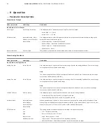
Menu: Alarm Output
Menu / parameter
Value range
Description
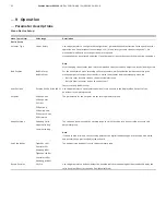
Input/Output / Alarm Output
Alarm Logic
Active High, Active Low
Use this parameter to define the contact logic for the alarm output.
• Active High –> I > 2.1 mA
• Active Low –> I < 1.2 mA
DO Alarm Mask
Alarm Maintenan., Alarm
OoSpec., Alarm Check Fct.,
Alarm Failure
Use this parameter to select which general alarms are output as an alarm current, depending on the
activated Namur classification group.
• Alarm Maintenan. – Maintenance needed
• Alarm OoSpec. – Operation outside specifications
• Alarm Check Fct. – Functional test needed
• Alarm Failure – Errors
Alarm Simulation
Off, Low, High
The presence of an alarm can be simulated here in order to output the alarm current.
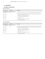
Menu: Analog Feedback
Menu / parameter
Value range
Description
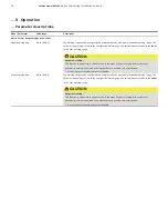
Input/Output / Analog Feedback
Analog Out Min.
4.0 to 18.4 mA
Use this parameter to specify the lower current range limit for the analog feedback. The current range
corresponds to the configured stroke range.
Note
The current range limits can be freely configured between 4 and 18.5 mA. However, the current range
must not be smaller than 10 % (1.6 mA).
Analog Out Max.
5.6 to 20.0 mA
Use this parameter to specify the upper current range limit for the analog feedback. The current range
corresponds to the configured stroke range.
Note
The current range limits can be freely configured between 4 and 20 mA. However, the current range
must not be smaller than 10 % (1.6 mA).
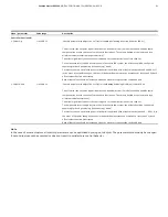
Feedbk. Charact.
Direct, Reverse
Use this parameter to specify the characteristic curve for the analog feedback.
• Direct
(rising)
= Position 0 to 100 % = Signal 4 to 20 mA
• Reverse
(falling)
= Position 0 to 100 % = Signal 20 to 4 mA
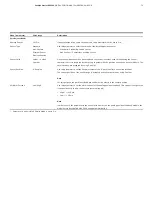
AO Alarm Mask
Alarm Maintenan.
Alarm OoSpec.
Alarm Check Fct.
Alarm Failure
When a general alarm is issued, an alarm current can be sent via the analog position feedback. These
alarm groups are defined in accordance with Namur NE107. A high alarm current ( ‘High’ i >21 mA), low
alarm current (‘Low’ I < 3.6 mA, or ‘Off’ can be set for each individual group.
AO Simulation
Off
Low
High
Input current
HW Alarm Current
The analog position feedback function is simulated in this parameter group.
• Off – Terminate simulation.
• Reverse – Alarm current I < 3.6 mA
• High – Alarm current I > 21 mA
• Input current – The input current of the positioner is output.
• HW Alarm Current – The ‘AO Alarm Current’ set in ‘Service Mode’ is output.


