

QUICK START GUIDE
Page 1
© 2021 ABB. All rights reserved.
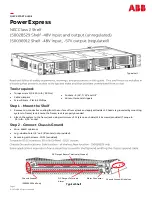
Power Express
NEC Class 2 Shelf
Tools required:
•
Torque wrench (0
-
240 in
-
lb / 28 Nm)
•
Cable crimpers
•
Screw Drivers
-
Flat & 2 Phillips
Step 1
-
Mount the Shelf
1.
Remove non
-
conductive coating from the surface of frame/rack and apply antioxidant. Chassis is grounded by mounting
system to frame/rack. Ensure the frame/rack is properly bounded.
2.
Attach the system to the frame/rack using a minimum of 12 (six on each side) 12
-
24 screws (provided). Torque to
35 in
-
lb
-
5/16”
socket.
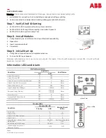
Step 2
-
Connect Chassis Ground
•
Wire
-
6AWG minimum
•
Lug
-
double
-
hole
1/4”
on
5/8”
centers (not provided).
•
Secure lug with screws
-
10
-
32 (provided)
Typical self
•
Sockets
-
5/16”, 7/16”
and
1/2”
•
Wire cutters and strippers
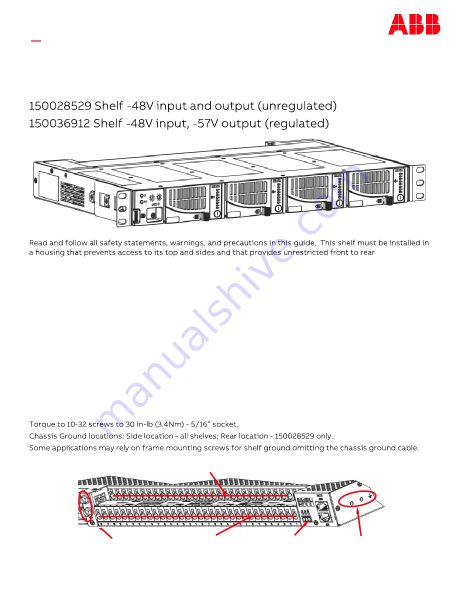
DC Output Terminals
Alarm
Chassis Ground
I50028529 Shelf only
Alarm Connector
Chassis Ground All shelves
DC Output Return Terminals (Ground)
Typical Shelf


