background image


QUICK START GUIDE


Page 4


© 2021 ABB. All rights reserved.


Warning: Shock Hazard and Equipment Damage 

-

 Equipment and subassembly ports


1.


are suitable for connection to intra

-

building or unexposed wiring or cabling;


2.


can be connected to shielded intra

-

building cabling grounded at both ends.
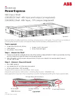
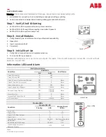
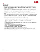
 

Step 7 

-

 Verify Shelf ID Setting


• 

Set Shelf ID to 00 to operate without a system controller.


• 

Set Shelf ID to 01 through 98 are read by a controller if present.


• 

Set Shelf ID to 99 to perform Lamp Test.


Step 8 

-

 Install Modules


1.


Verify Module Type 

-

 see Information: 8 port Module Compatibility


2.


Open latch.


3.


Insert module into Shelf.


4.


Close latch.


Step 9 

-

 Initial Start Up


1.


Verify that all connections are complete and secure.


2.


Turn on the DC input breaker.


Modules  automatically  start  up  and  scan  outputs  for  loads.  Circuits  with  loads  are  turned  ON,  circuits  without 

loads  are  turned  OFF.


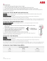
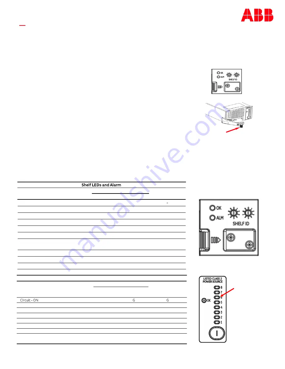
Information: LEDs and Alarm


Latch


Condition


Shelf LED


Shelf Alarm


OK


ALM


Class 2 Circuit ON


G


       OFF


Class 2 Circuit OFF


G


       OFF


Class 2 Circuit Over Current/Shorted


OFF


Y


Alarm


Class 2 Circuit Fail (1 or more)


OFF


        R


Alarm


Input Voltage Very Low


OFF


       OFF


Alarm


Input Voltage Out of Range


OFF


Y BLINK


Alarm


Reversed Input Polarity


OFF


R BLINK 


Y BLINK


Alarm


Alarm Card Fail


OFF


R


Alarm


Internal Shelf Comm Fault3


OFF


G


Alarm


GP Comm Fault


OFF


       R BLINK


Alarm


Alarm Card


Module LEDs


Condition


Module OK LED


Module Circuit 

LEDs

2


Priority

1


LED


Circuit 

-

 OFF


G


OFF


Circuit 

-

 ON 

-

 Over Current


3


Y


Y


Circuit 

-

 Fail


1


R


R


Comm Fault <

-

> Alarm Card


4


R BLINK


Per Circuit Condition


Module Fail


1


R


OFF


Input Voltage Out of Range


2


Y BLINK


OFF


Input Voltage Very Low or    


Reversed Polarity


OFF


OFF


Circuit LEDs


Summary of Contents for Power Express

Page 1: ...cure lug with screws 10 32 provided Typical self Sockets 5 16 7 16 and 1 2 Wire cutters and strippers DC Output Terminals Alarm Chassis Ground I50028529 Shelf only Alarm Connector Chassis Ground All shelves DC Output Return Terminals Ground Typical Shelf 150028529 Shelf 48Vinput and output unregulated 150036912 Shelf 48Vinput 57V output regulated Jl 1111 11111 1 0 0 Read and follow all safety stat...

Page 2: ...nce option see note below B5 Remove POS Lug Bridging Bus B6 Connect DC Input feed return to POSA lug landing B7 Connect Output Reference ground to POSB lug landing Without Remote Output Reference option B8 Connect to NEGA or NEGB lug landing 1 cable Torque All Lug Nuts B9 Torque all lug nuts to 65 in lb 7 3Nm 7 16 socket Notes Apply these options only when directed by the site engineering instruct...

Page 3: ... downward angle Pull the wire out of the terminal Wire Entry 24 8 gage 150036912 Negative 48V Positive ground 150028529 Step 5 Connect DC Outputs Connect DC Output and DC Output Return wires for each output 32 DC Outputs 8 per Module Step 6 Connect Alarm Cable 1 Remove alarm connector from the chassis 2 Connect alarm cable 3 Insert alarm connector into the chassis 1 Strip wire 3 16 2 Insert wire f...

Page 4: ...s with loads are turned ON circuits without loads are turned OFF Information LEDs and Alarm Latch Condition Shelf LED Shelf Alarm OK ALM Class 2 Circuit ON G OFF Class 2 Circuit OFF G OFF Class 2 Circuit Over Current Shorted OFF Y Alarm Class 2 Circuit Fail 1 or more OFF R Alarm Input Voltage Very Low OFF OFF Alarm Input Voltage Out of Range OFF Y BLINK Alarm Reversed Input Polarity OFF R BLINK Y ...

Page 5: ...Button to enter the manual mode hold until the OK LED turns OFF and back ON 2 seconds 1 Tap the Button repeatedly until the desired Circuit LED blinks 2 Press and hold the Button to toggle the circuit ON OFF hold until the OK LED turns OFF and back ON 2 seconds 3 Repeat from step 2 to operate another circuit 4 Automatic operation is restored after a few seconds of Button Inactivity The OK LED is t...

Page 6: ...ress dress to avoid damage to the conductors and undue stress on the connectors Fuses and Circuit Breakers Size as required by the National Electric Code NEC and or local codes Refer to the equipment ratings to assure current does not exceed Continuous Load List 1 60 of protector rating Maximum Load List 2 typically end of discharge 80 of protector rating Field wired Conductors Follow all National...

Page 7: ... with ringer modules hazardous voltages will be present on the ringer output connectors Use the following precautions in addition to proper job training and safety procedures Use only properly insulated tools Remove all metallic objects key chains glasses rings watches or other jewelry Follow Lock Out Tag Out LOTO procedures customer specified site specific or general as appropriate Disconnect all...

Page 8: ...ibility whatsoever for potential errors or possible lack of information in this document We reserve all rights in this document and in the subject matter and illustrations contained therein Any reproduction disclosure to third parties or utilization of its contents in whole or in parts is forbidden without prior written consent of ABB Copyright 2021 ABB All rights reserved ABB 601 Shiloh Rd Plano ...

Reviews: