Operation Manual / Power2 650-M / 4.1 Low-pressure stage
4 Disassembly and assembly / 4.13 Installing the wall insert
© Copyright 2020 ABB. All rights reserved.
HZTL4065_EN
Rev.C
March 2020
4. Fit two plates (90031) and secure with plate (90032), screw (90656) and nut (90432).
5. Lift the wall insert and remove the support angle (90480).
6. Carefully insert the wall insert.
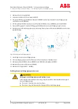
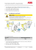
Fig. 27: Installing the wall insert 2
Part number
Tightening torque
72002
M16x334
50 Nm
Table 13: Tightening torque (72002)
1. Remove plate (90032), screw (90656), nut (90432) and plates (90031).
2. Remove the bracket (90030).
3. Detach speed measurement cable from provisional holder and insert cable con-
nector (86515).
4. Fit four studs (72002) in the upper area. Observe tightening torque.
Page
26
/
42


