Operation Manual / Power2 650-M / 4 Product description
1 Introduction / 1.3 Layout and function of the low-pressure stage
© Copyright 2020 ABB. All rights reserved.
HZTL4064_EN
Rev.E
March 2020
1.3
Layout and function of the low-pressure stage
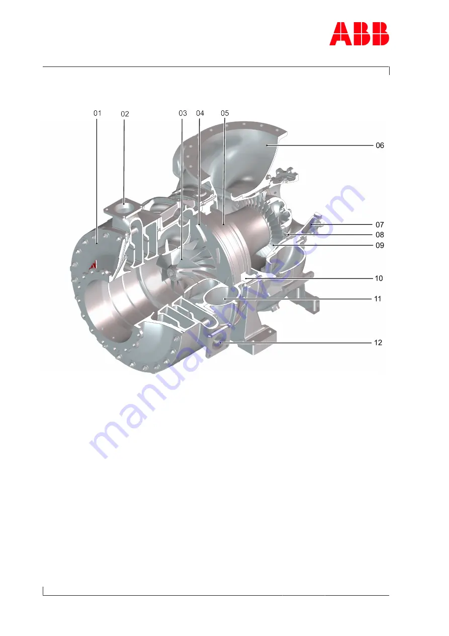
Fig. 2: Layout and function of the low-pressure stage
01
Air suction branch
07
Gas inlet casing
02 Injection ring for air
08
Nozzle ring
03 Compressor wheel
09
Turbine
04 Diffuser
10
Bearing casing
05 Bearing bush with heat shield
11
Compressor casing
06 Gas outlet casing
12
Injection ring for blowby
Page
6
/
51


