background image

26 

9

7

10

11

11

8

12

13

6

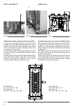
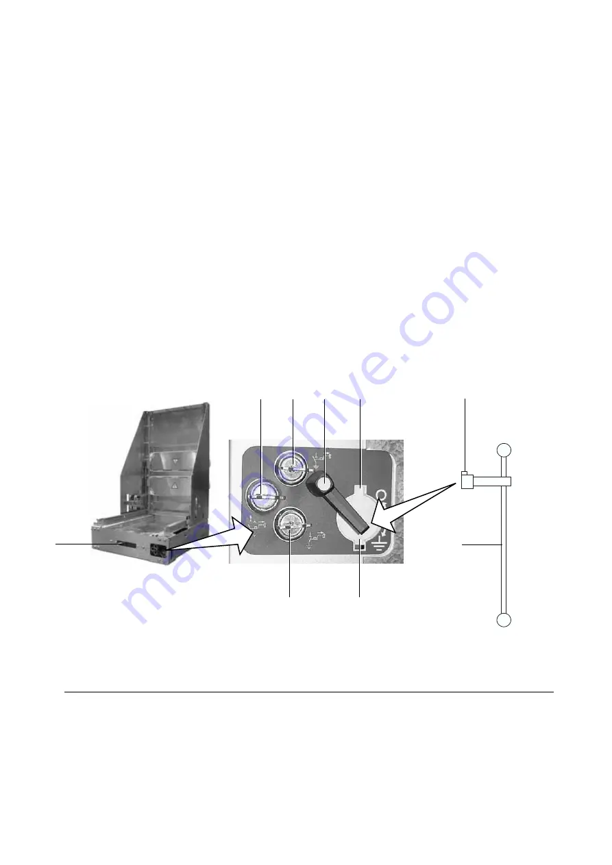
Fig. 14

Legenda dei blocchi a chiave del sezionatore di terra


7

   blocco a sezionatore di terra aperto


8

   blocco a sezionatore di terra chiuso


9

   blocco all’inserzione dell’interruttore.

Caption of the earthing switch key locks

  7 

lock with earthing switch open

  8 

lock with earthing switch closed

  9

  lock for preventing circuit-breaker insertion.

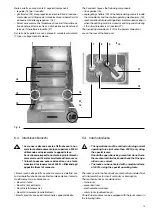
(2)  Passaggio dalla posizione di “sezionato in prova” a quello 

di “inserito” (con sezionatore di terra chiuso) (fig. 14).

– verificare che:
  •  sia alimentato il magnete di blocco del sezionatore di terra 

(se previsto);

  •  i blocchi  a  chiave (7-8-9) se previsti siano disattivati;
– inserire la leva di manovra (13) nella sede del sezionatore 

di terra  facendo coincidere il  risalto (12) con una delle due 
cave (11);

– aprire il sezionatore di terra  girando in senso antiorario la 

leva di manovra (13);

– estrarre la leva di manovra (13) dalla sede del sezionatore di 

terra;

– controllare attraverso l’oblò (6) che il sezionatore di terra sia 

aperto (indicatore in posizione “O”);

– chiudere l’otturatore della sede di manovra del sezionatore 

girando in senso orario l’attuatore (10); con questa manovra si 
sblocca l’interruttore e si aziona un blocco di impedimento per 
l’inserzione della leva di manovra nella sede del sezionatore 
di terra;

– verificare che sia alimentato il magnete di blocco sul carrello 

dell’interruttore  (se  previsto)  e  controllare  che  il  blocco  a  
chiave all’inserzione (se previsto) sia disattivato;

– inserire a fondo la leva di inserzione del carrello interruttore  

(3)  (fig.  12)  nel  corrispondente  innesto  e  ruotarla  in  senso 
orario finché l’interruttore è completamente inserito;

(2)  Switching from “test” to “connected” position (with earthing 

switch closed) (fig. 14)

– make sure that:
  •  the locking electromagnet of the earthing switch is energised 

(if supplied);

  •  the key locks (7-8-9) are de-energised, if supplied;
– insert operating lever (13) into the seat of the earthing switch  

making the raised piece (12) coincide with one of the two slots 
(11);

– open  the  earthing  switch,  turning  the  operating  lever  anti-

clockwise (13);

– withdraw  the  operating  lever  (13)  from  the  earthing  switch 

seat;

– through the inspection window (6) make sure that the earthing 

switch is open (indicator in the “O” position);

– close the cover of the earthing switch seat by turning the ac-

tuator (10) clockwise; this operation unlocks the circuit-breaker 
and trips a lock for preventing insertion of the operating lever 
into the earthing switch;

– make sure that the locking electromagnet on the circuit-breaker 

truck (if supplied) is energised and check that the key lock for 
preventing insertion (if supplied) is de-energised;

– fully insert the operating lever of the circuit-breaker truck (3) 

(fig. 12) in the relevant coupling and turn it clockwise until the 
circuit-breaker is fully connected;

b) Manovra di estrazione (solo a interuttore aperto)

(1) Passaggio dalla posizione di “inserito” a quella di “sezionato” 

(con interruttore aperto) (fig. 14)

– controllare che l’interruttore sia aperto (indicatore in posizione 

“O”); 

– inserire a fondo la leva di inserzione/estrazione del carrello/ 

interruttore  (3)  fig.  12  e  ruotarla  in  senso  antiorario  finché 
l’interruttore si arresta;  

b) Racking out operation (only with circuit-breaker open)

(1) Switching from “connected” to “isolated” position (with circuit-

breaker open) (fig. 14)

– make sure that the earthing switch is open (indicator in the 

“O” position); 

– fully insert the circuit-breaker truck/racking in/out lever (3)  (fig. 

12) and turn it anticlockwise until the circuit-breaker stops;

Summary of Contents for PowerCube PB/F

Page 1: ...chi e la sequenza manovre delle unità 24 7 Installazione 28 8 Messa in servizio 30 9 Controlli periodici 32 10 Operazioni di manutenzione 34 11 Accessori e parti di ricambio 36 Index 1 Packing and transport 4 2 Control on receipt 5 3 Storage 7 4 Handling 8 5 Description 10 6 Instructions for operating the apparatus and operation sequence of the units 24 7 Installation 28 8 Putting into service 30 ...

Page 2: ......

Page 3: ...ecessarie per un corretto intervento For your safety Make sure that the room is suitable for the installation of electrical apparatus Make sure that all the installation putting into service and maintenance operations are carried out by skilled personnel with in depth knowledge of the apparatus Makesurethatalltheinstallation serviceandmaintenance operations comply with standard and legal requireme...

Page 4: ...informazioni vedere anche il catalogo tecnico 1VCP000253 Per le istruzioni relative agli apparecchi interruttori contattori fare riferimento ai relativi libretti di istruzione Introduction The instructions in this manual refer to standardised Power Cube PB F medium voltage fixed parts For correct use of the apparatus please read the manual carefully PowerCube PB F fixed parts are designed for a la...

Page 5: ...pare parts 36 11 1 Accessories and tools for operations 36 11 2 Spare parts 36 Indice 1 Imballaggio e trasporto Pag 4 2 Controllo al ricevimento 5 2 1 Dati di targa 6 3 Magazzinaggio 7 4 Movimentazione 8 4 1 Parti fisse 8 5 Descrizione 10 5 1 Caratteristiche costruttive 10 5 2 Dimensioni e pesi 11 5 3 Componenti principali 17 5 4 Interblocchi blocchi 19 5 5 Norme di riferimento 23 6 Istruzioni per...

Page 6: ...o adeguati al peso di ciascun gruppo È doveroso prestare particolare attenzione e analizzare i rischi specifici operando in zone con linee aeree in tensione 1 Packing and transport Follow the symbols and instructions shown on the packing carefully Each fixed part is packed according to the shipping and storage requirements of the customer Each fixed part is protected by a plastic cover to prevent ...

Page 7: ...o al ricevimento Durante la movimentazione delle unità si racco manda di non sollecitare le parti isolanti Prima di eseguire qualsiasi operazione verificare sempre che le molle del comando siano scariche e l apparecchio in posizione di aperto Al ricevimento controllare immediatamente l integrità dell imbal laggio e lo stato delle apparecchiature Aprire l imballo come indicato al par 4 facendo atte...

Page 8: ... LIVELLO DI ISOLAMENTO NOMINALE Up 75 kV TENUTA IS A FREQUENZA INDUSTRIALE Ud 28 kV FREQUENZA fr 50 60 Hz CORRENTE NOMINALE Ir 1250 A CON VENTILAZIONE FORZATA ABB DESIGN Ir A CORRENTE DI BREVE DURATA Ik 31 5 kA CORRENTE NOMINALE DI PICCO Ip 80 kA DURATA DEL CORTO CIRCUITO tk 1 s SERIAL NUMBER YEAR 2006 IEC 60694 PowerCube PBF INSTRUCTION MANUAL 1VCD600530 RATED VOLTAGE Ur 12 kV RATED INSULATION VO...

Page 9: ...teriale impermeabile per es polietilene Nell imballo sono inseriti i sacchetti disidratanti che devono essere sostituiti circa ogni sei mesi Per particolari esigenze contattateci 3 Storage Please contact ABB in case of special storage conditions If the apparatus has to be stored before installation on request suitable packing for the conditions specified can be provided On receipt the fixed part m...

Page 10: ...ferably be carried out by means of bridge or mobile cranes Otherwise use rollers or fork lift trucks Weights and dimensions of the various sections are indicated in the shipping documents and on the plant drawings Fixed parts handling Caution To handle the fixed parts containing the ap paratus circuit breaker contactor or service truck it is compulsory to use the lifting eyebolts provided with the...

Page 11: ...Handling the module in the wooden crate Sollevamento del modulo Module lifting Fig 2 Fig 3 Fig 5 Movimentazione della parte fissa nell imballo in legno Lifting a fixed part packed in a wooden crate Movimentazione della parte fissa Fixed part handling Fig 4 ...

Page 12: ...IP2X a porta aperta 5 Description 5 1 Construction features The fixed parts allow MV switchboards with metal enclosure to be built suitable for indoor installation The fixed parts are pre assembled and tested in the factory The fixed parts are suitable for all primary distribution requirements with service voltages up to 24 kV and can take on different configurations according to customer requests...

Page 13: ...ted voltage 12 17 kV Test voltage at industrial frequency 28 38 kV Impulse withstand voltage 75 95 kV bil Short time withstand current 31 5 kA x 3s Peak current 79 kA Rated branch current 630 1250 A Earthing switch if requested Short time withstand current 31 5 kA x 3s Peak current 79 kA 5 2 Dimensioni e pesi Tipologie disponibili PowerCube PB1 F PB4 F adatti per unità tipo arrivo partenza e congi...

Page 14: ...contatti 35 mm 2 Diametro dei contatti 79 mm 1 Contact diameter 35 mm 2 Contact diameter 79 mm Un kV Icw kA In A TN 12 31 5 630 2000 1VCD003383 17 31 5 630 2000 1VCD003383 Disegni dimensionali a richiesta disponibili in formato elettronico Dimensional drawings available on request in electronic format Module PB4 F Typical use Rated voltage 24 kV Test voltage at industrial frequency 50 kV Impulse w...

Page 15: ...0 20 630 VD4 W 12 06 20 p210 VD4 W 17 06 20 p210 25 25 630 VD4 W 12 06 25 p210 VD4 W 17 06 25 p210 31 5 31 5 630 VD4 W 12 06 32 p210 VD4 W 17 06 32 p210 16 16 1250 VD4 W 12 12 16 p210 VD4 W 17 12 16 p210 20 20 1250 VD4 W 12 12 20 p210 VD4 W 17 12 20 p210 25 25 1250 VD4 W 12 12 25 p210 VD4 W 17 12 25 p210 31 5 31 5 1250 VD4 W 12 12 32 p210 VD4 W 17 12 32 p210 20 20 1600 VD4 P 12 16 20 p210 VD4 P 17...

Page 16: ...4 W 12 16 25 p210 HD4 W 17 16 25 p210 31 5 31 5 1600 HD4 W 12 16 32 p210 HD4 W 17 16 32 p210 16 16 2000 HD4 W 12 20 16 p210 HD4 W 17 20 16 p210 25 25 2000 HD4 W 12 20 25 p210 HD4 W 17 20 25 p210 31 5 31 5 2000 HD4 W 12 20 32 p210 HD4 W 17 20 32 p210 24 16 16 630 HD4 W 24 06 16 p210 PB 4 F 20 20 630 HD4 W 24 06 20 p210 25 25 630 HD4 W 24 06 25 p210 16 16 1250 HD4 W 24 12 16 p210 20 20 1250 HD4 W 24...

Page 17: ... 17 16 20 p210 25 25 1600 VM1 P 12 16 25 p210 VM1 P 17 16 25 p210 31 5 31 5 1600 VM1 P 12 16 32 p210 VM1 P 17 16 32 p210 20 20 2000 VM1 P 12 20 20 p210 VM1 P 17 20 20 p210 25 25 2000 VM1 P 12 20 25 p210 VM1 P 17 20 25 p210 31 5 31 5 2000 VM1 P 12 20 32 p210 VM1 P 17 20 32 p210 24 1 16 16 630 VM1 P 24 06 16 p210 PB 4 F 20 20 630 VM1 P 24 06 20 p210 25 25 630 VM1 P 24 06 25 p210 16 16 1250 VM1 P 24 ...

Page 18: ...riore e terra Ø Diametro dei contatti presenti nel monoblocco delle unità PowerCube tipo PB Per la disponibilità chiedere ad ABB W Width of fixed part P Horizontal centre distance between circuit breaker poles u l Distance between top and bottom terminal H Distance between bottom terminal and earth Ø Diameter of the contacts in the PB type PowerCube unit monobloc For availability ask ABB Corrente ...

Page 19: ...ecchi sono fissati gli scivoli per l azionamento delle serrande di segregazione dei contatti di media tensione Per ulteriori dettagli fare riferimento ai relativi libretti di istruzione 5 3 Main components 5 3 1 Switchgear PowerCube modules can be equipped with the following switchgear HD4 series SF6 circuit breaker VD4 VM1 eVM1 and Vmax series vacuum circuit breaker V Contact series vacuum contac...

Page 20: ...rthing switch is indicated by the yellow arrow made directly on the operating shaft 5 The position of the earthing switch can be checked either by means of the indicator 3 located inside the enclosure and visible through the inspection window 4 positioned on the bottom front part of the unit 5 3 3 Descrizione parte fissa La struttura metallica aperta dispone esternamente sul lato anteriore degli o...

Page 21: ...on superiore a 200 N utilizzando esclusivamente le apposite leve Serisultasseroimpedite nonforzaregliinterblocchi meccanicieverificarelacorrettezzadellemanovre I blocchi possono essere azionati con una forza massima di azionamento di 400 N utilizzando gli appositi attrezzi di manovra I blocchi usati nelle parti fisse sono meccanici ed elettrici con microinterruttori che danno continuità o interrom...

Page 22: ...i apparecchi solo con gli apparecchi in posizione di sezionato è possibile attivare il blocco e liberare la chiave impedendo l inserzione degli apparecchi Key lock to prevent apparatus insertion Only when the apparatus is in the isolated position can the lock be operated and the key released thus preventing apparatus insertion Blocco a chiave con sezionatore di terra aperto si può attivare solo co...

Page 23: ...21 6 2 4 2 6 5 3 1 2 3 4 5 6 7 1 Fig 9a Fig 9b Fig 9 ...

Page 24: ...must be carried out by the customer by closing the holes not used with the special plugs according to the coding enclosed with this manual Codifica del connettore spina presa dei circuiti ausiliari La codifica del connettore spina presa dei circuiti ausiliari permette di abbinare elettricamente gli apparecchi al proprio pannello Per esempio permette di abbinare apparecchi con correnti nominali div...

Page 25: ... in high voltage electrical apparatus Codifica connettore spina per connettore a 58 poli 10 1 Presa cablaggio di comando 10 4 Punti di centratura dei pin Interruttori e contattori Circuit breakers and contactors 12 17 5 kV 600 mm 750 mm 400 A V Contact 630 A VD4 VM1 HD4 VD4 VM1 HD4 1250 A VD4 VM1 HD4 VD4 VM1 HD4 1600 A VD4 VM1 HD4 2000 A VD4 VM1 HD4 Carrelli di sezionamento Isolating trucks 12 17 ...

Page 26: ...va di manovra dei sezionatori di terra 2 Leva carica molle dell interruttore 3 Leva di inserzione estrazione interruttore 4 Risalto della leva di manovra Fig 12 6 Instructions for operating the apparatus and operation sequence of the units Donotremovethecircuit breakercoveringpanels if necessary keep a safe distance during appara tus opening and closing operations to avoid any contact with moving ...

Page 27: ...quadro Assicurarsi che le maniglie siano scattate lateral mente blocchi orizzontali del carrello inseriti nel contenitore Fig 13a 6 2 Apparatus racking in out Should any operation be carried out while the circuit breakeriswithdrawnfromtheswitchboard pay the utmost attention to the moving parts The circuit breaker must be inserted into the unit only in the open position its racking in out must be g...

Page 28: ...witching from test to connected position with earthing switch closed fig 14 make sure that thelockingelectromagnetoftheearthingswitchisenergised if supplied the key locks 7 8 9 are de energised if supplied insert operating lever 13 into the seat of the earthing switch making the raised piece 12 coincide with one of the two slots 11 open the earthing switch turning the operating lever anti clockwis...

Page 29: ...o orario l attuatore di comando 10 con questa manovra si sblocca l interruttore e si aziona un blocco di impedimento per l inserzione della leva di manovra nel sezionatore di terra open the cover of the earthing switch operating seat by turning the actuator anticlockwise 10 insert the operating lever 13 in the earthing switch seat making the raised part 12 coincide with one of the two slots 11 clo...

Page 30: ... The PB F fixed part must be considered a compo nentforbuildingswitchgears Thefixedpartcannot be used or commissioned as loose component 7 2 Normal installation room conditions Maximum air temperature 40 C Minimum air temperature 5 C Relative humidity 95 Altitude 1000 For other installation room characteristics please refer to the product standards IEC 60694 For any special conditions please conta...

Page 31: ...C Inentrambiicasi larealizzazionedelcollegamento a curadelcliente deverispettarelageometriaindicata in figura affinchè sia garantito il potere di chiusura del sezionatore di terra 7 4 Connection of the lower terminals for units with earthing switch with and with out CT The PowerCube units are preset for connection of the CTs between the A and C contacts of the lower terminals If this is not done c...

Page 32: ...the apparatus and try the racking in operation Conapparecchioinposizionedisezionatoruotare la chiave di 90 With the contactor in the isolated position turn the key 90 Con apparecchio estratto tentare di spostare manualmente le serrande With apparatus withdrawn try to manually move the shutters CONTROLLO POSITIVO POSITIVE TEST Manovre e segnalazioni regolari Normal operations and signals La chiusur...

Page 33: ...arthing switch cannot be closed La manovra risulta impedita dopo circa due giri di manovella The operation is prevented after about two handle turns Risultaimpeditalapossibilitàdiinserirelalevadimanovra del sezionatore di terra The earthing switch operating lever cannot be inserted Risultaimpeditalapossibilitàdiinserirelalevadimanovra del sezionatore di terra The earthing switch operating lever ca...

Page 34: ...nto prescritto all articolo 10 della norma IEC 60694 In ogni caso per eventuali problemi non esitate a consultarci Si consiglia comunque un ispezione all apparecchiatura non oltre un anno dell entrata in servizio della stessa 9 Periodic checks The periodic checks must be carried out by skilled personnel Before carrying out any operation make sure that the apparatus is open with springs discharged ...

Page 35: ...ti Check device functionality Verificare che i contatti siano esenti da deformazioni erosioni e ossida zioni Lubrificare gli elementi di contatto con grasso tipo Molydal EL 5 Industrial Service oppure con grasso di vaselina Check that contacts are not deformed eroded or oxidised Lubricate the contacts with Molydal EL 5 Industrial Service grease or Vaseline Controllare il serraggio e l assenza di t...

Page 36: ...elmodulo escludendogliapparecchi per i quali si rimanda ai relativi manuali di istruzione 10 Maintenance operations Maintenance must be carried out either by our personnel or by qualified skilled personnel Should the customer s personnel be in charge of maintenance the customer is responsible for any operation performed on the apparatus Whileperformingroutinechecksandmaintenance operations de ener...

Page 37: ...cchiatura interbloccata Se nell azionamento del dispositivo si nota un eccessivo sforzo significa che il dispositivo è impedito nel suo movimento in questo caso contattateci 10 2 Metallic structure This comprises the supporting construction complete with verti cal and horizontal segregating sheets These parts are galvanised Galvanised components The galvanised and passivated components can be clea...

Page 38: ...gli apparecchi vedere le relative istruzioni di installazione esercizio e manutenzione Per la parte fissa è previsto il sezionatore di terra con montaggio a cura del cliente 11 Accessories and spare parts Either our personnel or qualified skilled customer personnel must mount the spare parts and or the accessories carefully following the instructions enclosed Before performing any operation make s...

Page 39: ......

Page 40: ...14542 Glindow Phone 49 0 2102 12 1230 Fax 49 0 2102 12 1916 E mail calor info de abb com www abb com Dati e immagini non sono impegnativi In funzione dello sviluppo tecnico e dei prodotti ci riserviamo il diritto di modificare il contenuto di questo documento senza alcuna notifica The data and illustrations are not binding We reserve the right to make changes without notice in the course of techni...

Reviews: