Section-1
04-3004_S1_OPM_ABB_POWERSCALE_10-50kVA_EN_150113.doc
Page 19/20 ABB
Printed in Switzerland
– Modifications reserved
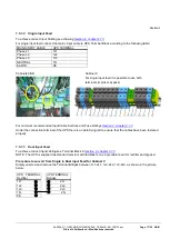
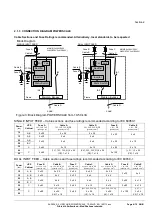
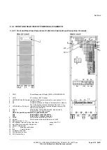
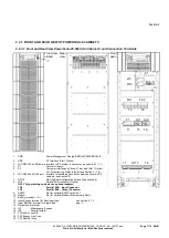
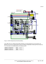
Dual Input Feed connections for Cabinet A,B,C
For dual input feed connect the mains input cables to UPS Terminal according to following tables:
MAINS INPUT CABLE
UPS TERMINAL
Rectifier
BYPASS INPUT CABLE UPS TERMINAL
Bypass
Phase L1
1L1
Phase L1
2L1
Phase L2
1L2
Phase L2
2L2
Phase L3
1L3
Phase L3
2L3
NEUTRAL
1N
NEUTRAL
2N
EARTH
PE
EARTH
PE
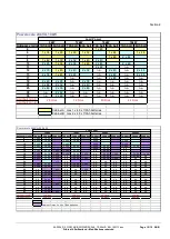
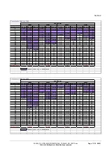
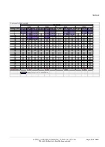
For minimum recommended Input Cable Sections and Fuse Ratings
1.5.1.4
Preparation for the Output Cabling
Before you start connecting the loads, ensure that the UPS rated powers (OUTPUT POWER) on the nameplates
(on the front side of the UPS) is equal to or larger than the total load requirements.
The output of the UPS must be fitted with circuit breakers or other kind of protection. These circuit breakers will be
connected between the loads and the UPS and will provide additional protection to the UPS in the event of
overloads and short circuits.
These circuit breakers will enable the protection of each load separately.
The size of the circuit breakers depends on the load rating of the load sockets.
The circuit breakers must comply with the prescribed IEC Standards. It is recommended to provide a separate
output distribution board for the load.
The following values should be indicated on the output distribution board:
Maximum total load rating;
Maximum load rating of the load sockets.
If a common distribution board is used (sockets for Mains and UPS voltage), ensure that on each socket there is
an indication of the applied voltage (“Mains” or “UPS”).
Output power cable ratings should be in accordance with the recommended cable sections and fuses ratings or in
accordance with the prescribed IEC Standards or with the local regulations.
Ensure that the earth connection is performed in accordance with the prescribed IEC Standards or with the local
regulations.
1.5.1.5
Connection of the Load
To ensure protection of the personnel during the installation of the UPS make sure that the connections are
performed under the following conditions:
No mains voltage is present;
All loads are shut down and disconnected;
UPS is shut down and voltage-free.
Before connecting the output power cables make sure that:
UPS is placed in its final and correct position;
Maintenance bypass is in position OFF;
Parallel Isolator IA2 is in position OFF
Remove the terminal cover of the UPS.
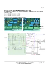
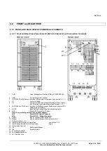
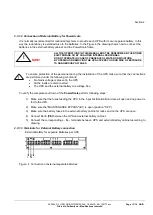
Connect the output power cable coming from the LV-Distribution Board to the terminals of the UPS as shown in
drawing in
(Front view of the PowerScale)


