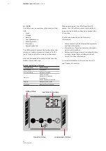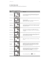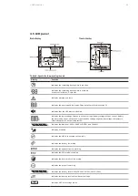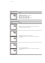
12
POWERVALUE 11 RT G2 IN —
6-10 KVA
12
A B B U PS PRODUC TS A N D SOLUTION S
—
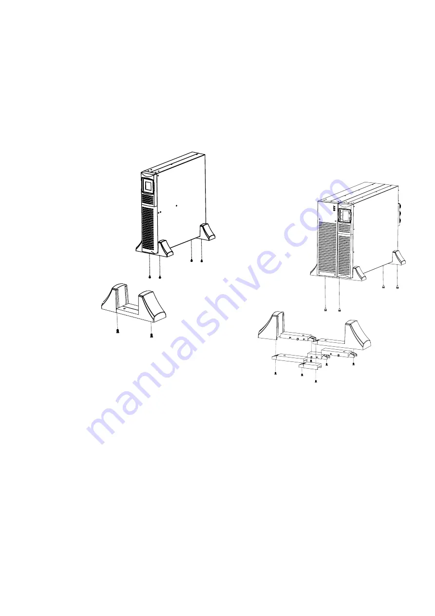
7 Stabilizer bracket for
external batter module
3.2.4.2 External battery modules
1. Set up the extension plate as below and install
it on the UPS stabilizer bracket.
2. Install the UPS and EBM individually into the
stabilizer bracket.
3. Connect to the UPS with the battery power
cable (refer to rack position installation).
Note:
It is recommended that this unit be installed to
UPS’s righthand side.
If installing an additional unit, place it next to
the previous unit.
—
06
11
3 .2 .3 .2 External battery modules
Identify the final position and keep 3U spacing
for this installation; it is recommended that this
spacing is provided below the UPS.
1. Install the ear bracket onto the unit with the
flathead M4 screw. (figure 1).
2. Slide the unit into the rail kit and make sure to
tighten the rack-mounting screw (figure 3).
3. Connect the EBM to the UPS with the battery
power cable (figure 4).
NOTE
UP TO FOUR EXTERNAL BATTERY
ENCLOSURES CAN BE CONNECTED TO
THE UPS IN THE SAME WAY AS
SHOWN ABOVE.
NOTE
AFTER CONNECTING THE BATTERY
ENCLOSURES, CONFIGURE THE NUMBER
OF BATTERY MODULES IN THE CONTROL
PANEL (FOR MORE INFORMATION SEE
CHAPTER 4.6.7). SEE APPENDIX C FOR
FURTHER DETAILS.
—
05
—
04
—
04 Battery module
connection
—
05 Display rotation
—
06 Stabilizer bracket for
external batter module
3 .2 .4
Standalone / tower installation
3 .2 .4 .1 UPS
1. Set up the stabilizer bracket then put the unit
into the stabilizer bracket.(figure 5).
3 I N S Ta L L aT I O N
3.2.4 Standalone / tower installation
3.2.4.1 UPS
1. Set up the stabilizer bracket then put the unit
into the stabilizer bracket.(figure 5).
—
05
Display rotation
3.2.4.2 External battery modules
1. Set up the extension plate as below and install
it on the UPS stabilizer bracket.
2. Install the UPS and EBM individually into the
stabilizer bracket.
3. Connect to the UPS with the battery power
cable (refer to rack position installation).
—
06
Stabilizer bracket for external battery module
Note:
It is recommended that this unit be installed to
UPS’s righthand side.
If installing an additional unit, place it next to
the previous unit.
Summary of Contents for PowerValue 11 RT G2 IN
Page 1: ... USER MANUAL PowerValue 11 RT G2 IN 6 10 kVA ...
Page 2: ......


