Operating instruction manual
| IR10/PP10 Field Indicator and Controllers 3
1.0 Introduction
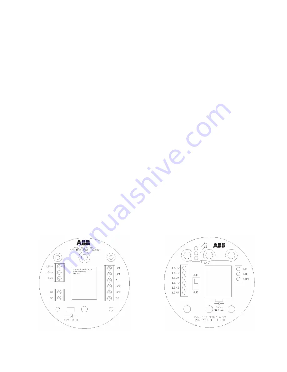
The ABB IR10 Interposing Relay (AC or DC Relay) Output Module is designed for use in applications such that certain pro-
cess control equipment may require a higher operating current thatn can be supplied by various ABB (or other manufactur-
ers’) switch products. The module can be used for applications requiring control of on/off devices such as motors, motor
starters, solenoids and alarms. The IR10 consists of printed circuit board mounted relay and three terminal blocks. It is
supplied in an explosion proof enclosure (Class 1, Division 1). The unit is generally powered by 120 VAC, although other
operating voltages are available. The module accepts one set of DPDT dry contacts as an output (NO and NC contacts).
The ABB PP10 Latching Relay Controller is designed for use in applications requiring control of on / off devices
such as motors, motor starters, solenoids and alarms. The Pump-Pak is a control device consisting of a PC board
mounted relay and associated components. The PP10 is supplied in an explosion proof enclosure (
Class 1, Division
1
) and is available with an optional mounting hardware kit. The PP10 is generally powered by 120 VAC, however,
other operating voltages are available. The PP10 accepts one set of contact inputs and provides a dry contact input
(NO and NC contacts).
1.1 Function
The IR10 operates as a simple interposting relay, actuated by an external limit switch. The relay will energize when a closed
contact is sensed at the input terminal. When used for a motor, solenoid or alarm function, the input power is supplied to
the IR-10 via a DC or AC connection. The input power is isolated from the output contacts. Two IR-10s can be configured to
operate four isolated process devices. A circuit can be configured in a “fail-safe” mode such that a power failure will cause
a high level alarm.
The PP10 operates as a simple start / stop control circuit, actuated by external limit switches. High or low level operation is
selected via a miniature switch located on the circuit board. The on-board relay operates as follows: In the HLO (to empty
a tank) position, relay K1 energizes when the high level limit is tripped and then deenergizes when the low level limit is
reached. In the LLO (to fill a tank) position, relay K1 energizes when the low level limit is tripped and then deenergizes when
the high level limit is reached. In the event of power failure with the relay energized, the PP10 unit will revert back to proper
operation after one cycle of the level limit switches.
IR10
PP10

