6 IR10/PP10 Field Indicator and Controllers |
Operating instruction manual
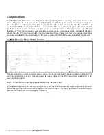
One use of the IR10 is motor and motor starter control. This figure illustrates the proper connection of the IR10 for
controlling a motor driven device. Operating power is usually supplied to the IR10 via customer provided AC or DC
power distribution panel.
Note:
The that the IR10 operating power is isolated from the motor circuit.
In the above configuration, the IR10 will energize the motor driven device when the high high level limit is tripped.
It will deenergize the motor driven device when the level limit is reset. This circuit, for example, could be used for
pumping fluid from a tank in an emergency condition.
4.1 IR10 Motor or Motor Starter Control
4.0 Applications
The ABB IR10 and PP10 Relays are designed to simplify most applications requiring pump motor and solenoid
control. They can also be used to provide adjustable deadband (hysteresis) for alarms and other control applica-
tions. The following diagrams should help provide applications information on how to utilize the IR10 or PP10. It is
assumed that ABB latching level switches are used in all of the following application diagrams. Please not that the
deadband (hysteresis) of the limit switches shown may be so small that the controlled device will cycle (on-off) more
than desired. This condition would be very prevalent on small vessels. In situations where controlled deadband is
desired, the ABB PP10 controller would be the more desirable choice. Please note that these sample applications
are supplied to assist in the understanding of the relay operation and that ABB assumes no liability for their use.

