Manual Power Quality Filter PQFS
Mechanical design and installation 31
5.3
Airflow and cooling requirements
The PQFS dissipates an amount of heat that has to be evacuated out of the room where
the filter is located. Otherwise, excessive temperature rise may be experienced. Please
note that life of the electrical equipment decreases drastically if the operating
temperature exceeds the allowable limit (divided by 2 every 10°C/23°F).
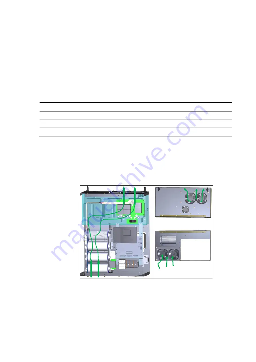
Each PQFS power unit has its own cooling fans. The air intakes are located at the bottom
of the unit. From the bottom, the air flows through the enclosure and is then routed to
the top of the enclosure. For proper cooling, a minimum airflow of cooling air has to be
supplied to each unit.
gives the airflow requirements for different unit ratings.
Table 15: Airflow requirement
Unit rating
Airflow requirement (m³/h)
30A - 60A
520 m³/h
70A - 100A
520 m³/h
120A
710m³/h
Please ensure that the air used for cooling is regularly renewed and does not contain
conductive particles, significant amounts of dust, or corrosive or otherwise harmful
gases. The cooling air intake temperature must not exceed 40°C under any operating
condition. The hot exhaust air also has to be properly ducted away.
cooling air flow diagram for a single unit PQFS.
Bottom view
Top view
Figure 17: Cooling air flow for a single unit PQFS
When the natural cooling capacity at the location where the filter is installed is not
sufficient, air conditioning systems have to be installed to the room. In the design of the
air conditioning systems, the filter heat losses have to be taken into account.
gives an overview of the PQFS heat losses for the different power units. For multi-unit
filters, the values of


