38 Electrical design and installation
Manual Power Quality Filter PQFS
Every filter has been tested for insulation between the main circuit and the
chassis/frame at the factory. Therefore, do not make any voltage tolerance or insulation
resistance tests (e.g. hi-pot or megger) on the inverter units. Check the insulation of the
assembly by measuring the insulation resistance of the filter between the Protective
Earth (PE) and all 3 phases shorted together, with main contactor shorted. The auxiliary
fuse box may remain closed, but it is mandatory to disconnect P2 (24V supply), P3
(230Vac in), P4 (PQF-Manager if master), P12 (IGBT) and P20-P21 (to other units) from
the main control board (see
WARNING: Making the test without disconnecting the abovementioned connectors
may damage the filter.
Use a measuring voltage of 500 Vdc. The insulation resistance must be higher than
500 k
Ω
per enclosure.
6.4
EMC considerations
The CE version of active filter complies in its standard version with the following EMC
guidelines:
−
EN/IEC 61000-6-2: Immunity standard for industrial environments, Industrial
level.
−
EN/IEC 61000-6-4: Emission standard for industrial environments, Class A.
6.5
Earthing guidelines
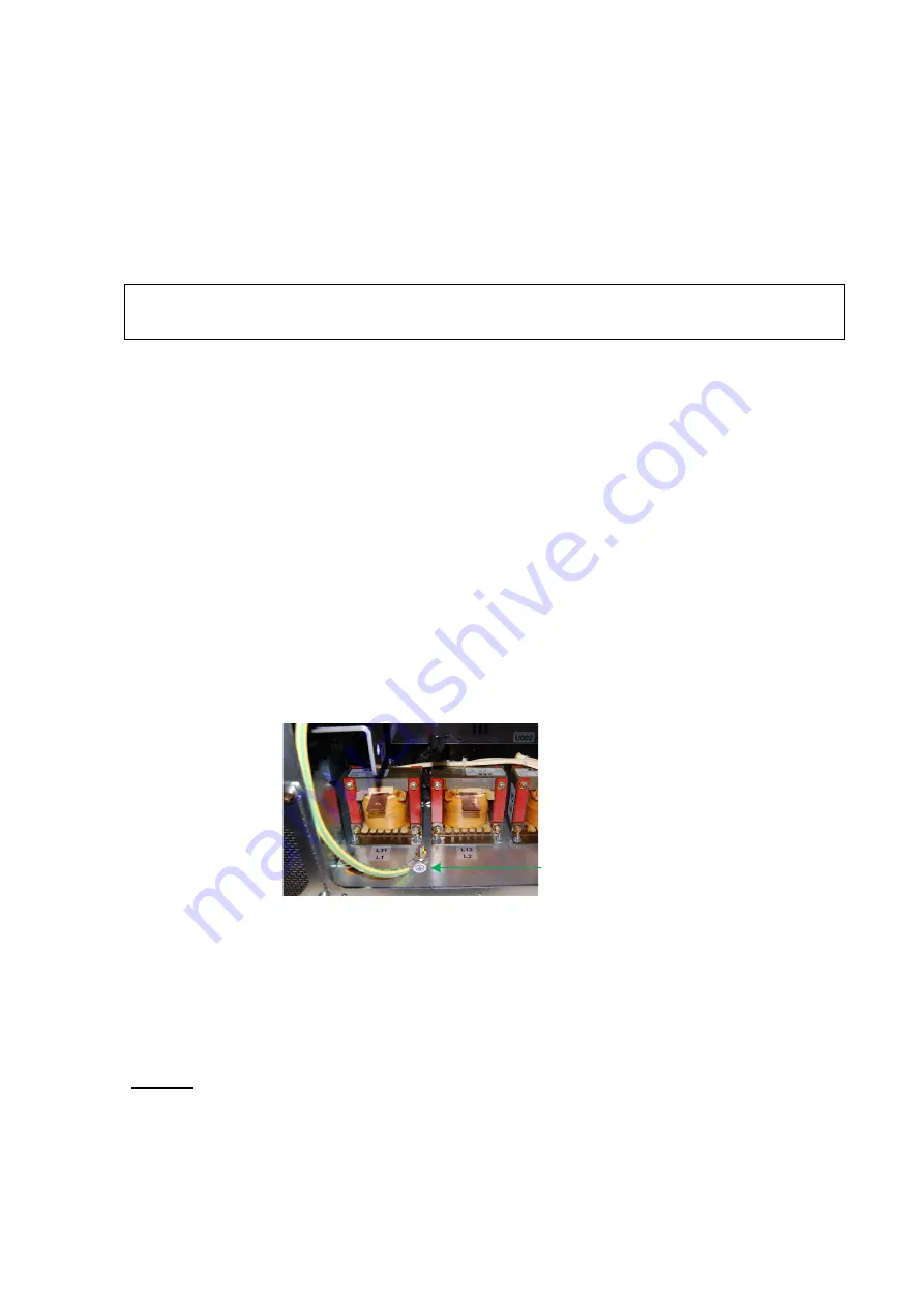
Each PQFS plate has one marked earth points (PE). The earth point is situated at the
bottom right side of the filter plate (
Earth point (PE)
Figure 25: Identification of the earth point on the PQFS hardware
For safety reasons and for proper operation of the filter the earth point of each
enclosure must be connected to the installation’s earth (PE). A copper (Cu) cable of
minimum size 16 mm² is recommended but local regulations should also be taken into
account.
Remark: in PEN systems, the earth connection of the filter must be connected to the
installation’s earth (PE) and not to the N-conductor.
Further, the following rules should be respected:
−
When the PQFS consists of only one enclosure, the enclosure’s PE-point must be
connected directly to the installation’s PE-point.


