background image

USER I N T ER FAC E 

11

Enabling 

Auto start

 will allow your module to  

restart automatically in the event of a power out-
age (or any event that causes the inverter to trip). 

Auto st. Del.

 sets how long the module will re-

main off before it attempts to restart. If 

Auto 

start

 is disabled, the module will not restart  

automatically after a power outage.

3.5.2 Clock

Set the Clock to your local time to calibrate the 
time signature of events and faults when they are 
recorded in Events Logging (Section 3.7.3).

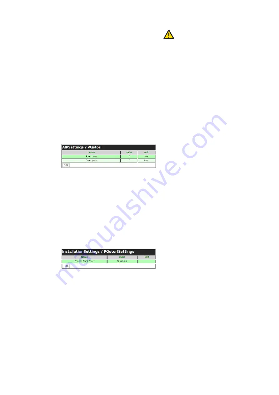
3.5.3  PQstorI

Define 

P set point

 and 

Q set point

 to target the 

real and reactive power desired on the network. 
The PQstorI will inject power onto the network in 
efforts to meet these targets.

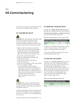
3.6 Installation settings

3.6.1 Network Characteristics

Set 

V nominal

 to the nominal phase-phase  

voltage on the grid and set Frequency to either  
50 or 60 Hz.

3.6.2 AIP Characteristics

Set the 

Connection type

 to 

3-wire.


I Nominal

 dis-

plays the current capacity of the PQstorI module.

The nominal power is the rated module power. 
Even when operating multiple modules in parallel, 
enter the rating for a single module (i.e. 30 kW for 
smaller PQstorI units).

3.6.3 CT Settings


PQstorI can measure the line currents in the main 
feed of the grid. These signals will be used for 
functionalities to be released in the future. When 
adopting this option, the CT Settings page of the 
Wi-Fi user interface will attribute each sin-
gle-phase lines from the CT to a connection ter-
minal on the module. By default, line 1 connects to 

CT input [0],

 line 2 to 

CT input [1]

 and line 3 to 

CT 

input [2].

 CT Ratio L1-3 displays the ratio of pri-

mary current on your electrical network to the 
secondary current running through the module. 
 

3.6.4 Auto CT Detection


To determine the ratio and position of the CT au-
tomatically, set 

StartAutoCT

 to Start. Low bat-

tery voltage can reduce the Auto CT detection ca-
pability of the PQstorI.

3.6.5 Derating


At high altitude or under high temperature,  
you can maintain safety standards and the lifes-
pan of your equipment by reducing its power.  
Set Derating to the percentage calculated in  
Section 5.6.


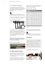
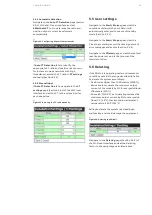
Figure 7: User settings for the PQstorI


Figure 8: User settings for the PQstorI

Summary of Contents for PQstorI

Page 1: ...ENERGY STOR AGE INVERTERS PQstorI Installation operation and maintenance instructions...

Page 2: ...5 User settings 3 6 Installation settings 3 7 Monitoring 3 8 System settings 3 9 Modbus commands 04 Installation 4 1 Upon reception 4 2 Location 4 3 Identification tag 4 4 Mechanical installation 4 5...

Page 3: ...easurements 6 3 Checking system faults 6 3 Retrieving manufacturer data 07 Maintenance 7 1 Maintenance intervals 7 2 Check system faults and operating hours 7 3 Cleaning and tightening screws 7 4 Repl...

Page 4: ...lternating current voltage AC 4 5 2 Direct current voltage DC 4 5 3 Grounding 4 5 1 Phase connection 4 5 2 DANGER These safety instructions are intended for all work on the PQstorI range of products N...

Page 5: ...urement of the AC voltage across 1 pole of the islanding contactor breaker not functional at present Section 4 5 4 Output to control the islanding contactor breaker Section 4 5 4 Input for the 24Vdc s...

Page 6: ...strating the internal components of the PQstorI product Figure 3 Block diagram of main PQstorI components E L1 DC DC L2 L3 N1 N2 24V EXT 24V INT 24 V DC FUSES DC RELAYS DC BUS POWER MODULE LCL FILTER...

Page 7: ...Green LED on and steady Module is on or starting up Red LED blinking Module has encountered a critical error Green and red steady Firmware is updating Yellow LED blinking Wi Fi traffic 2 4 LEDs The g...

Page 8: ...through the Wi Fi user interface click the Edit button at the bottom of a settings page in Figure 5 input your changes in the Value column of the settings table in Figure 6 and click the Save button i...

Page 9: ...l component of all line currents 3 4 3 AIP Irms L1 3 RMS value of the 3 phase inverter current 3 4 4 AIP Irms N RMS value of the neutral inverter current 4 wire mode P Active power on the network at t...

Page 10: ...a similar way to the table for the voltage spectrum 3 4 4 Device Currents AIP Irms L1 3 reports the RMS value of the current injected into each phase line of the network and AIP Irms N reports the cu...

Page 11: ...wer is the rated module power Even when operating multiple modules in parallel enter the rating for a single module i e 30 kW for smaller PQstorI units 3 6 3 CT Settings PQstorI can measure the line c...

Page 12: ...of the PQstorI only operation on grid connected is available so that will be status shown in the AIP Monitoring window Battery Voltage is the DC voltage across the battery ter minals and Battery Curr...

Page 13: ...uld not be preloaded The voltage increase on the DC capacitors during the preload phase is not high enough Inverter trips reset required DC Top over voltage The DC over voltage protection of the capac...

Page 14: ...ps reset required DSP timeout DSP didn t give any feedback within 2 seconds after a start stop request command was sent to it Inverter trips reset required Heart beat timeout AIP has stopped upon rece...

Page 15: ...dministrators to set the Hostname Realm IP Address and Network Mask of the Wi Fi network emitted by the module to connect to the user interface Set the Wi Fi mode to Access Point to connect directly t...

Page 16: ...Float 2 0 3200 The rms voltage measured between the phases L2 and L3 L2 and Neutral when connected in 4 wire mode VrmsL3L1 30505 V Float 2 0 3200 The rms voltage measured between the phases L3 and L1...

Page 17: ...tDSPError for the list of possible DSP errors Islanding Status 36201 Dword 2 0 2 When set 1 means that unit is in Islanding mode when cleared 0 it is in grid connected mode Available in the future Bla...

Page 18: ...positive when discharging the battery Udc Inverter DC voltage 30523 V Float 2 0 3200 The DC voltage present on the inverter DC bus Name Address Unit Type Register length Range Description Min Max Star...

Page 19: ...ion Make sure that you transport store and operate the product within the range of temperature a Up to 50 C 122 F with auto derating b Locations with normal levels of contaminants experienced in urban...

Page 20: ...used for the power cabling of the inverter The maximum cable size that can fit into these terminals is 25 mm2 The wiring methods for electrical installation of the inverter shall be in accordance wit...

Page 21: ...k start islanding functions not available yet The black start board includes supercaps to enable the inverter to ride through low voltage interruptions while still providing energy for the control cir...

Page 22: ...e operating conditions of the PQstorI require class 1 0 X 5A CT that can withstand 15 VA over 20 meters of 2 5 mm2 14AWG cables Insert each CT wire into the appropriate pole of the spring contact fema...

Page 23: ...it is not mechanically or electrically damaged and that it can tolerate the voltage on the electrical network Close the upstream protection for powering the module If the cabling is correct the red s...

Page 24: ...ry addi tional 1 C 1 8 F Maximum allowed ambient temperature is 50 C 122 F Failing to derate the system risks leading to malfunction and could damage the equipment Navigate to the Derating page Sectio...

Page 25: ...ty to provide and continuously ensure a secure connection between the product and user network or any other network as the case may be User shall establish and maintain any appropriate measures such a...

Page 26: ...current and voltage on each line on the electrical network navigate to the Voltages and Line Current pages of the Wi Fi user interface as described in Sections 3 4 2 and 3 4 3 respectively 6 3 Checkin...

Page 27: ...nths 7 3 Change cooling fan 40 000 hours of operation 7 4 07 Maintenance 7 2 Check system faults and operating hours Navigate to the page on Event Logging of the Wi Fi user interface to check for rece...

Page 28: ...if it has been damaged if the system is overheating or after 40 000 hours of operation You can order fan replacement kits from your ABB supplier To replace the fan Unscrew the three screws on the fron...

Page 29: ...condensing during operation Max 85 non condensing during storage Pollution Degree PD2 Overvoltage Category OVC III AC OVC II DC Altitude Indoor installation in clean environment at 1000m upto 5000m w...

Page 30: ...ly open 5 A 30 VDC Mechanical aspects Mounting Modules suitable to integrate into a cabinet on draws or as part of a rack system with push connectors Wall mounted Dimensions W x D x H 435 x 459 x 130...

Page 31: ...cle code a Module 1 M Software version b Wi Fi user interface controller software DSP software Installation location 9 1 Module identification Remarks a Read from main identification tag located on th...

Page 32: ...eck the setting and operation of the protective apparatus Check tightness of conductor fixations The material of terminals and conductors must be compatible corrosion Installation a Check the voltage...

Page 33: ...le terminal Input 1 is connected to the CT including sign a Line 1 2 3 1 2 3 Module terminal Input 2 is connected to the CT including sign a Line 1 2 3 1 2 3 Module terminal Input 3 is connected to th...

Page 34: ...the current of the inverter Check the power absorbed by the inverter Check the batteries voltage through the BMS Check the batteries current through the BMS Set the P setpoint to 0 Set up the user req...

Page 35: ...warn Prog alarm 2 T crtl warn Prog alarm 3 V min warn Alarm delay V max warn Alarm rst del Imbalance Ground fault Start Stop Settings Prog Warnings Stdby status Prog warn 1 Standby level Prog warn 2 S...

Page 36: ...ument without prior notice With regard to purchase orders the agreed particulars shall prevail ABB does not accept any responsibility whatsoever for potential errors or possible lack of information in...

Reviews: