20
PQSTOR I
I N S TR U C TI O N M A N UA L
—
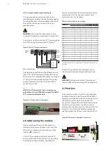
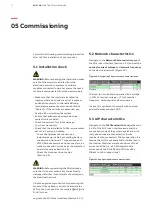
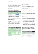
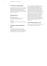
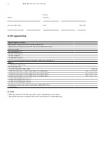
Figure 14: Mounting modules on the wall
4.4 Mechanical installation
The PQstorI range of products can be installed either in a cabinet or mounted on a wall as illustrated
in Figure 14.
Fix the mounting kit by tightening 12 screws
to the side panels of the module and screw the
mounting kit to a wall that can support over 20
kilograms of electrical equipment. You can order
wall installation kits from your ABB supplier.
For cabinet assembly the clearances below must
be followed:
•
Front of the inverter: minimum of 600mm
(radius of the front door of the cabinet/
minimum corridor width for passage of
personnel)
•
Rear: 200mm if no forced air flow in place
(horizontal air flow)
•
Air flow requirement: 266m³/h per unit needed
when using forced airflow (vertical airflow)
4.5 Electrical connections
WARNING:
The PQstorI range of products can tol-
erate network voltages of up to 415 V for a 3-wire
configuration. Never connect these products to a
network that will sustain extended periods of
over-voltage (+10%).
Only copper cables rated for 75
o
C or above are
allowed to be used for the power cabling of the
inverter. The maximum cable size that can fit
into these terminals is 25 mm
2
.
The wiring methods for electrical installation of
the inverter shall be in accordance with the Na-
tional Electrical Code and with ANSI/NFPA70.
4.5.1 Earth connection
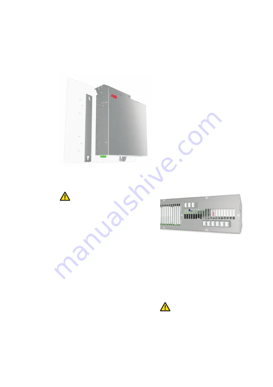
Ground the PQstorI connecting an earth cable
with an appropriate cross-section (minimum
10 mm
2
) to the ground terminal (PE) on the back
of the module (Figure 15). Tighten its screw to a
torque of 3 - 5 N.m.
—
Figure 15: Earth, AC and DC power connection to
the PQstorI
4.5.2 Power supply (AC)
Connect the module to an AC power supply by
screwing power cables of an appropriate
cross-section to each phase-line terminal on its
back panel (Figure 15). Tighten each screw to a
torque of 3 - 5 N⋅m.
Make sure that the voltage phase rotation at the
power supply remains clockwise (L1 (R, U) -> L2
(Y, V) -> L3 (B, W) -> L1 (R, U)).
WARNING:
For safety reasons, when using a
phase rotation meter, the phase rotation must be
measured at the upstream protection level and
not in the module itself. The internal power con-
nections of the PQstorI inverter are isolated from
the earthing. Thus, it is installer's responsibility
to ensure that the AC supply system is earthed
and an earth cable must be connected in the in-
verter's earth terminal
DC
+
-
N N L3 L2 L1 PE


