21
I N S TA L L AT I O N
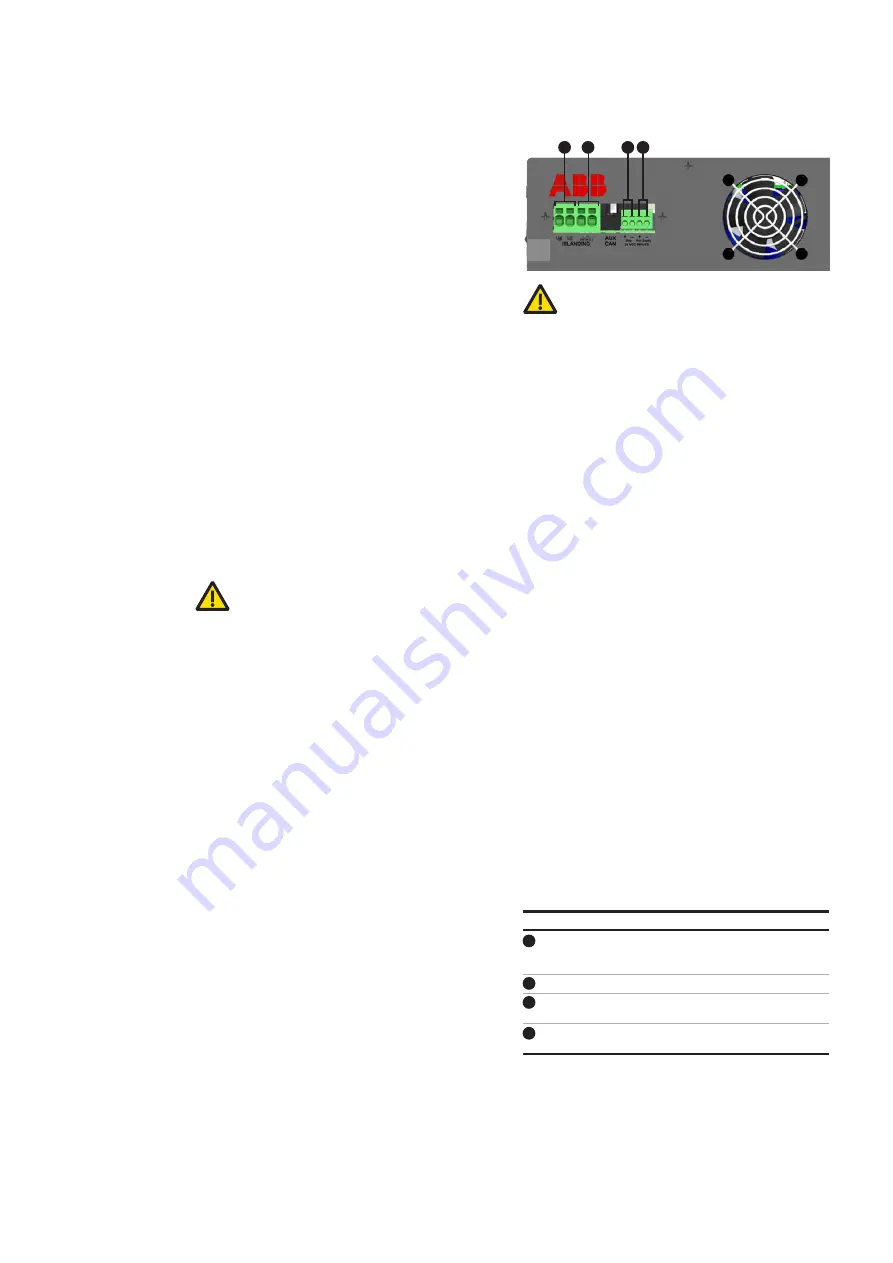
Components of the black start board
Measurement of the AC voltage across 1
pole of the islanding contactor/breaker
(not functional at present)
Islanding dry contact to control the main breaker
Input for the 24Vdc emergency
stop signal (mandatory)
Input for 24 Vdc power supply for extended
low voltage interruption (optional)
—
Figure 16: Black start board
—
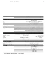
Table 14: Connection terminals on the black start board
11
12
13
14
When powered, the module will automatically
check the phase rotation. If the power cables are
connected incorrectly, the module will not start,
the status button of the Wi-Fi user interface will
turn yellow (Section 4.1.3) and a message indicat-
ing wrong phase rotation will appear in Event
Logging (Section 4.1.7.3). Correct the phase rota-
tion before supplying power to the module to
avoid a potential malfunction or damage to the
equipment.
4.5.3 Battery
Connect the battery to the DC terminals on the
back of the PQstorI. Make sure that the positive
(+) terminal of the inverter is connected to the
positive (+) terminal of the battery (Figure 16). In-
verting the polarities will result in the error mes-
sage Global Battery Voltage Error (Section
4.1.7.4).
The PQstorI requires no external DC protection.
However, follow instructions provided by the bat-
tery supplier for any protection needed by the en-
ergy storage system and make sure that the in-
stallation meets local regulations for cable
protection.
Do not
ground the battery terminals.
4.5.4 Black start board
The inverter has a board (10 in Figure 2) with ter-
minals that interface with customer's system in
the matter of grid code compliance in some coun-
tries. This board is called as "blackstart board" as
it is intended to be used in the future for black
start/ islanding functions (not available yet).
The black start board includes supercaps to
enable the inverter to ride through low voltage
interruptions while still providing energy for the
control circuit without the use of an external
24Vdc supply (minimum 15sec holdup with fault
repetition less than 5 sec depending on the volt-
age depth). This function is comply with grid
code requirements (LVRT).
The black start board enables parallel connection
of a 24Vdc emergency stop signal (terminals 13 in
Figure 16 – MUST CONNECT) which interconnects
via the NS protection relay to comply with some
grid code requirements. Under normal operation
the inverter must receive a 24Vdc signal between
the terminals and, in case of an emergency stop,
the 24Vdc shall go to 0Vdc and the inverter has its
E-Stop function activated.
WARNING:
Even if the e-stop function is not re-
quired by local grid code, this e-stop connector
must be wired with 24 Vdc.
The blackstart board enables connection of an
external 24Vdc supply for extended low voltage
interruption beyond 15 seconds where it may be
required by local grid code requirements. Note
that with the external 24Vdc supply connected,
the supercaps of the black start PCBA are not
charged.
It also includes an islanding dry contact (termi-
nals 12 in Figure 16) for the main BESS breaker to
trip in an event of an active islanding detection by
the inverter. This function is also part of some
grid code requirements and might be connected
when applicable. The terminals 11 are not func-
tional and will be used for future functionalities
of the PQstorI inverter.
—
NOTE: The terminals 12 are suitable for cables
with cross-section from 0.5 mm² (20AWG) to
10mm² (8AWG). Only copper cables rated for 75°C
or above are allowed to be used. The terminals 13
and 14 are suitable for cables with cross-section
from 0.5 mm² (20AWG) to 2.5mm² (14AWG). Only
copper cables rated for 75°C or above are allowed
to be used.
11
12
13 14


