


33
PQSTOR I
I N S TR U C TI O N M A N UA L
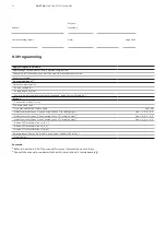
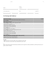
Apply voltage to the module
(a)
Apply voltage to the module (restore upstream protection)
Connect to Wi-Fi user interface, start the module, status button turns red
Fans start running
Program equipment
(b)
Network characteristics
- Supply voltage (V)
- Supply frequency (Hz)
- Synchro mode (should normally not be changed, default value is Single ph.)
Ratings
-
Connection mode (3-wire)
CT position and ratio
- Automatic detection feature used
YES/ NO
-
Module terminal ‘Input 1’ is connected to the CT (including sign)
(a)
Line 1, 2, 3, -1, -2, -3
-
Module terminal ‘Input 2’ is connected to the CT (including sign)
(a)
Line 1, 2, 3, -1, -2, -3
-
Module terminal ‘Input 3’ is connected to the CT (including sign)
(a)
Line 1, 2, 3, -1, -2, -3
-
Ratio of CT installed in line L1 (R, U)
-
Ratio of CT installed in line L2 (Y, V)
-
Ratio of CT installed in line L3 (B, W)
Derating factor (temp > 40°C/ 104°F or altitude > 1000m/ 3300ft or…)
-
Derating (%)
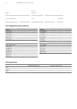
9.3 Programming
Remarks:
(a)
Refer to Section 4.5.3 of the manual for more information on this topic.
(b)
Consult the manual provided with the HMI installation kit (sold separately).
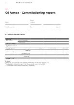
Project:
PQstorI
Issued by:
Commissioning report
Date:
Page 3 of 6


