


I M P O R TA N T S A FE T Y I N S T R U C T I O N S | G E T T I N G TO K N O W YO U R P R O D U C T
5
Item
Component
Manual section
AC power supply terminal (mandatory)
Section 4.5.2
Main earth connection point (mandatory)
Section 4.5.1
CT connection terminal (optional)
Section 4.5.5
Manual button (start/ stop/ acknowledge fault)
Section 2.5
System LEDs
Section 2.4
Micro-USB connection for firmware update and troubleshooting
n/a
DIP switch to set the address of modules operated in parallel
Section 4.6.1
RJ12 terminals (RJ12 #1 and #2) for CAN communication between modules and
to connect to the PQconnecT (CAN/ Modbus converter)
Section 4.6
DC power supply terminal (mandatory)
Section 4.5.3
Black start board
Section 4.5.4
Measurement of the AC voltage across 1 pole of the islanding contactor/ breaker
(not functional at present)
Section 4.5.4
Output to control the islanding contactor/ breaker
Section 4.5.4
Input for the 24Vdc signal of the Emergency Stop function of the
Battery Energy Storage System
Section 4.5.4
Input for external auxiliary 24 Vdc power supply (optional)
Connector to be used for future functionalities
—
02 Getting to know your product
2.1 Product components
The PQstorI is a product of the Advanced Inverter
Platform (AIP) range. Its external connection
terminals and signalling features are listed in
Table 1 and depicted in Figures 1 and 2.
Figure 3 depicts the internal components of
this product.
—
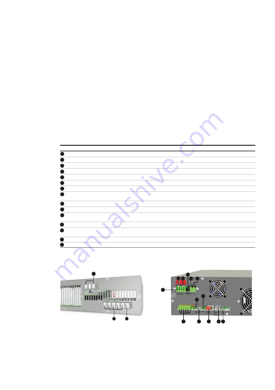
Table 1: External connection terminals and signals on PQstorI
—
Figure 1: Back connections
—
Figure 2: Front connections
1
2
1
2
3
3
4
4
5
5
5
6
6
7
7
8
8
9
9
10
10
11
11
12
12
13
13
14
15
14
15


